Current limiting device based on quick converting switch and liquid metal current limiting device, current limiting method therefor

A liquid metal and current limiting device technology, applied in the field of electrical switchgear, can solve the problems of long time to return to the superconducting state, lower automation level, poor reliability, etc., and achieve good electrothermal stability, dynamic stability, and fast response time , contact reliable effect

Inactive Publication Date: 2009-03-25
XI AN JIAOTONG UNIV
View PDF2 Cites 33 Cited by
  • Summary
  • Abstract
  • Description
  • Claims
  • Application Information

AI Technical Summary

Problems solved by technology

However, the application technology of superconducting materials for high-power applications is still immature and the reliability is poor. At the same time, it takes a long time for superconductors to return to the superconducting state, so it is generally difficult to meet the requirements of automatic reclosing and other aspects, and liquid nitrogen is also required for recovery. And other auxiliary refrigerants and refrigeration equipment, the additional loss is large, etc.
[0007] The current-limiting fuse is currently the only commercialized fault current limiter. The short-circuit current can be forcibly limited before reaching

Method used


Image

  • Current limiting device based on quick converting switch and liquid metal current limiting device, current limiting method therefor
  • Current limiting device based on quick converting switch and liquid metal current limiting device, current limiting method therefor
  • Current limiting device based on quick converting switch and liquid metal current limiting device, current limiting method therefor

Examples


Embodiment Construction

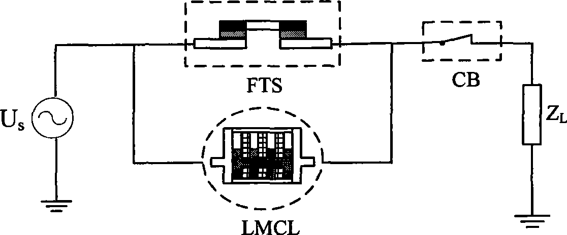
[0027] Overall structural features and working principle of the present invention

[0028] Such as figure 1 As shown, the present invention connects the fast transfer switch (FTS) and the liquid metal current limiting device (LMCL) in parallel and then connects them in series with the circuit breaker (CB).

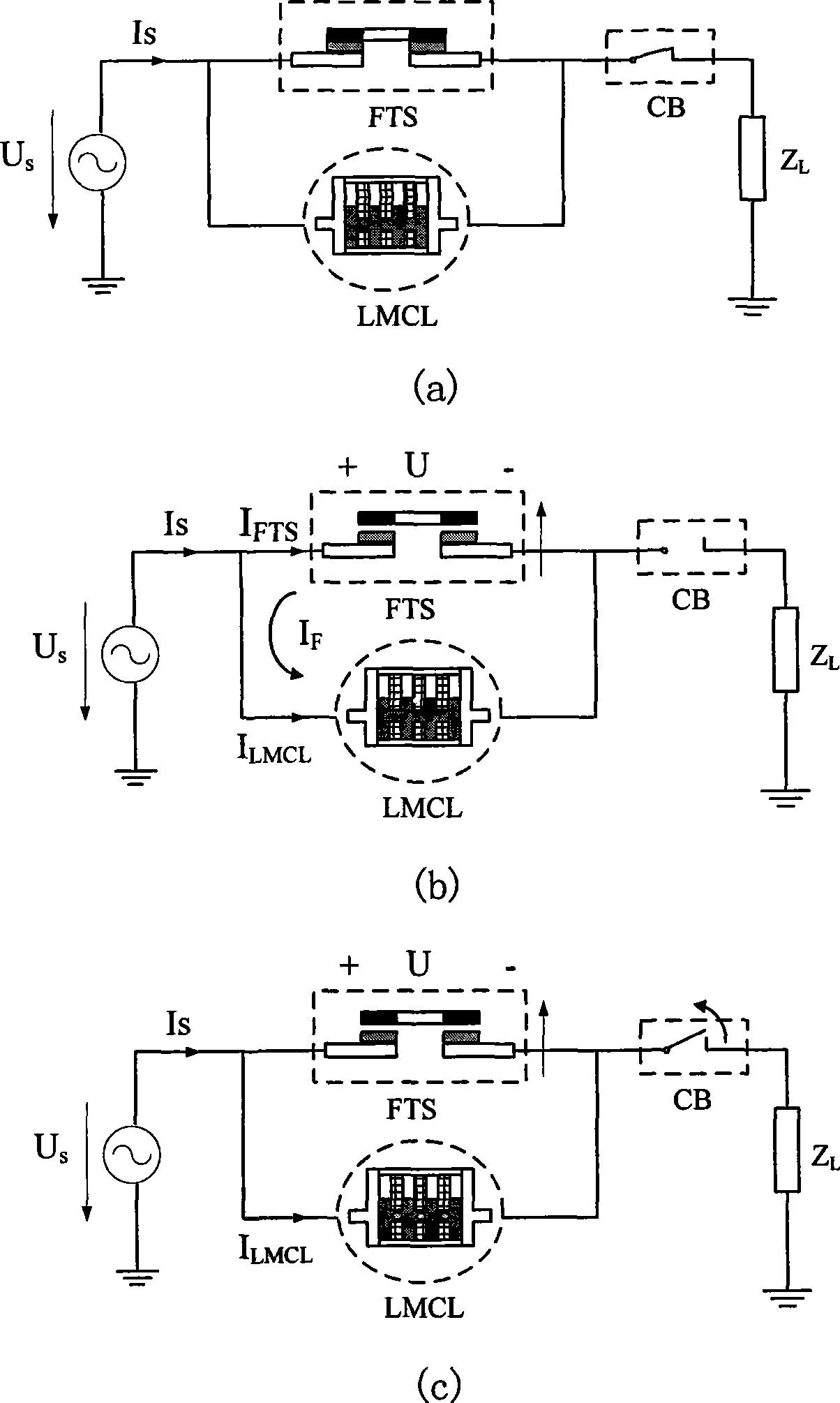
[0029] It works like figure 2 :

[0030] (a) When the line is in normal working condition, the resistance of the liquid metal current limiting device (LMCL) is larger than the resistance of the bridge contact in the fast transfer switch (FTS), so most of the current flows through the fast transfer switch (FTS). There is almost no loss in the line;

[0031] (b) Line load Z L A short-circuit fault occurs at the place, the charging circuit 11 of the disc coil 9 (see Image 6 The thyristor SCR in ) is turned on quickly, and the precharged capacitor C discharges to the disk coil 9, generating a pulse current i that lasts for several milliseconds q , under the action of t...


PUM


Abstract

Based on a quick switcher and a liquid metal flow restricting device and a flow restricting method, the quick switcher is connected with the liquid metal flow restricting device in parallel and then connected with a circuit breaker in series. Under normal working circumstances, most of the currents can flow through the branch circuit in which the quick switcher is arranged nearly without loss; and once the short circuit current error occurs, a repulsion force mechanism quickly drives a connecting rod to cause a bridge contact to realize quick disjunction, and the currents are gradually transferred to the branch circuit in which the liquid metal flow restricting device is arranged. When the liquid metal flow restricting device restrains the short circuit currents to a range which the circuit breaker can open and close, the circuit breaker can open and close the short circuit currents. The invention has a simple structure, is particularly suitable for restraining the error currents in middle-lower pressure field AC/DC system, and can reduce the burden of various electrical devices such as circuit breaker.

Description

technical field [0001] The invention relates to the main technology for electrical switchgear, and is applicable to the technology for limiting the fault current of AC and DC systems in the field of medium and low voltages, in particular to a current limiting device and method based on a fast transfer switch and liquid metal. Background technique [0002] With the increase of power system capacity year by year, the short-circuit capacity and short-circuit current level of the power grid are also increasing, which has become an important problem restricting the operation and development of the power grid. Therefore, research on effective short-circuit current limiting devices to limit the short-circuit capacity of the power system and improve the reliability of the power system has become an urgent issue for the safe and stable operation of the power system and the construction and development of power systems in my country. So far, the technologies applied to short-circuit c...

Claims


Application Information

Patent Timeline
IPC IPC(8): H02H9/08H01H71/24H01C11/00
Inventor 吴翊荣命哲刘懿莹杨飞刘宏潘晨曦王小华
Owner XI AN JIAOTONG UNIV
Why Eureka
Try Eureka