Light input/output port of optical component and beam converting apparatus

A technology for optical components and conversion devices, applied in the coupling of optical waveguides, etc., can solve the problems of heating optical fibers, high energy density of incident light, damage, etc., and achieve the effect of reducing fusion loss, manufacturing cost, and manufacturing

Inactive Publication Date: 2009-03-25
FURUKAWA ELECTRIC CO LTD
View PDF4 Cites 6 Cited by
  • Summary
  • Abstract
  • Description
  • Claims
  • Application Information

AI Technical Summary

Problems solved by technology

When the cladding mode light propagates in the cladding layer 594 and reaches the fiber coating portion 595, since the energy density of the incident light is high, it may heat the fiber coating portion 595 and cause damage.

Method used


Image

  • Light input/output port of optical component and beam converting apparatus
  • Light input/output port of optical component and beam converting apparatus
  • Light input/output port of optical component and beam converting apparatus

Examples


Embodiment Construction

[0080] The structure of the optical input and output ends of the optical component according to the preferred embodiment of the present invention will be described in detail with reference to the drawings. In addition, the same code|symbol is attached|subjected and shown about each structural part which has the same function in order to simplify illustration and description.

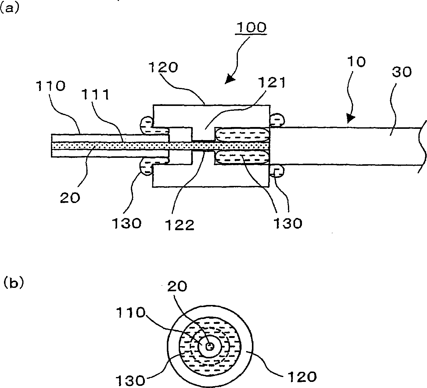
[0081] figure 1 It is a schematic diagram showing the configuration of the optical input and output ends of the optical component according to the embodiment of the present invention. figure 1 (a) is a side sectional view of the optical input / output end 100 of this embodiment, figure 1 (b) is a front view of the optical input / output terminal 100 viewed from the left side of the drawing. In this embodiment, an optical fiber as an example of a waveguide that is an optical component will be described, and an optical input and output end of the optical fiber will be described.

[0082] exist figure 1...


PUM


Abstract

A light input/output terminal module 100 comprises a jacket tube 110 and a flange 120. A glass portion 20 of the optical fiber is inserted in the center portion thereof. To efficiently remove the leaked light in a cladding 22 to the jacket tube 110, the jacket tube 110 is made of silica glass or the same material as that of the cladding 22. The jacket tube 110 is fixed by fusion splicing or adhesion to the cladding so as to integrally unify the jacket tube 110 and the cladding 22. The beam diameter at the fiber end portion is enlarged by an optical component which fusion bonds the tip end of the optical fiber to the coreless fiber so that the optical power density at the light input/output terminal module is reduced.

Description

technical field [0001] The present invention relates to the structure of an optical input / output port (optical coupling portion) of an optical component, and more particularly relates to the structure of a light input / output port used in a spatial coupling system optical component for high-output light transmission. Furthermore, the present invention relates to a beam conversion device for parallelizing and focusing light. In particular, it relates to a beam conversion device used in an optical component for high-power light transmission capable of enlarging the beam diameter at the end of an optical fiber. Background technique [0002] In recent years, in the field of optical communication systems, in response to the spread of WDM transmission systems capable of large-capacity transmission, higher output of optical power used has been developed, and it is considered that such a trend of higher output (several W level) will continue further up. [0003] In addition, in the...

Claims


Application Information

Patent Timeline
Patent Type & Authority Applications(China)
IPC IPC(8): G02B6/26G02B6/32
Inventor 渡边慎吾山垣美惠子畑野达也水野一庸田中完二藤崎晃
Owner FURUKAWA ELECTRIC CO LTD
Why Eureka
Try Eureka