Camshaft flank hole processing clamp

A side hole and camshaft technology, which is applied in the direction of manufacturing tools, metal processing equipment, metal processing machinery parts, etc., can solve the problems of side hole processing accuracy, low efficiency of clamping methods, and unsuitable for mass production.

Inactive Publication Date: 2009-04-01
TAIZHOU HONGXIANG POWER MACHINERY
View PDF0 Cites 13 Cited by
  • Summary
  • Abstract
  • Description
  • Claims
  • Application Information

AI Technical Summary

Problems solved by technology

At present, the machining of the side hole of the camshaft usually adopts the method of positioning and clamping the outer circle of the small end of the camshaft and the movable pin. Due to the machining error of the outer circle of the small end

Method used


Image

  • Camshaft flank hole processing clamp

Examples


Embodiment Construction

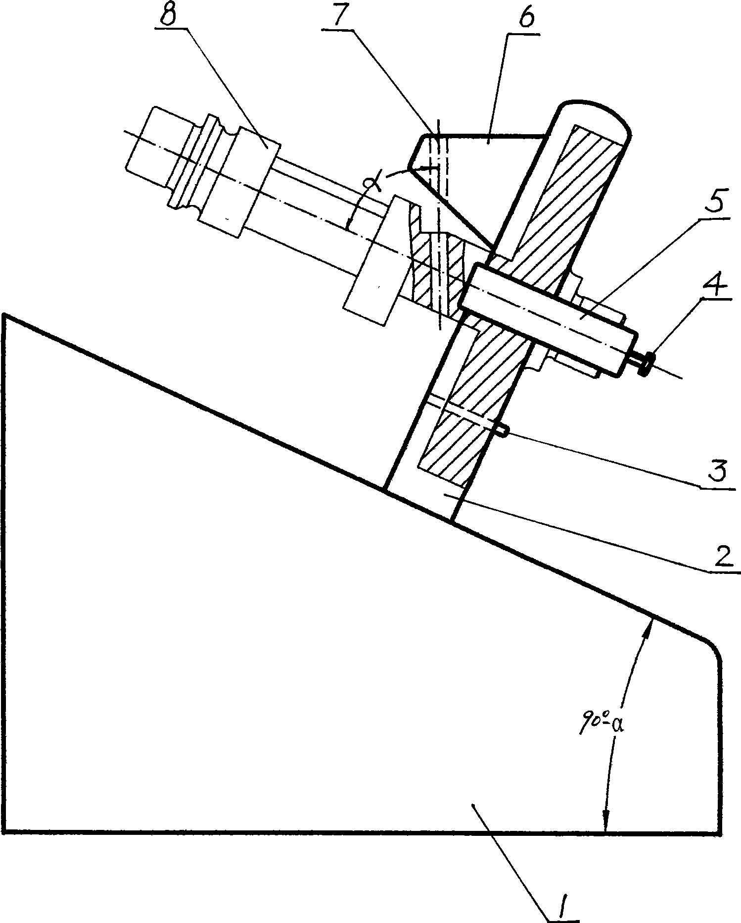
[0008] Referring to the accompanying drawings, the upper plane of the base 1 forms an inclination angle of 90°-α with the bottom plane, where α is the angle between the side hole on the camshaft 8 and the axis of the camshaft, and the positioning plate 2 fixed on the upper plane of the base is perpendicular to the upper Plane, forming an oblique angle α with the bottom plane of the base, the middle part of the positioning plate has a positioning hole perpendicular to the positioning plate and a positioning pin 3 below the positioning hole, the end surface of the positioning hole forms an oblique angle α with the bottom plane of the base, and 5 sets of hook-shaped sliding pressure plates On the positioning plate, it can move up and down, the pressing plate is provided with a compression screw 4, the positioning plate is provided with a drill sleeve 6 above the positioning hole, and the drill sleeve has a guide hole 7 perpendicular to the bottom plane of the base.


PUM


Abstract

The invention discloses a camshaft side surface hole processing clamp; a positioning plate which forms an oblique angle Alpha with the bottom surface of a base is arranged above the base; the middle position of the positioning plate is provided with a positioning hole vertical to the positioning plate and a positioning pin which is arranged below the positioning hole; one side of the positioning plate is provided with a movable pressing plate and a pressing screw. Further improvement of the camshaft side surface hole processing clamp is characterized in that the movable pressing plate is a hook-shaped sliding pressing plate which is sheathed on the positioning plate; the positioning plate is provided with a drill sleeve which is arranged above the positioning hole. The camshaft side surface hole processing clamp is used for processing the side surface hole on the camshaft in a gasoline engine, has convenient assembly and disassembly and small positioning error, can improve the processing efficiency and processing precision and is suitable for batch production.

Description

technical field [0001] The invention relates to a drilling fixture, in particular to a camshaft side hole machining fixture. Background technique [0002] The camshaft is an important part of a general-purpose gasoline engine. The side hole of the camshaft has an inclination angle α with the camshaft axis, and has a center distance requirement from the gear end face at one end of the camshaft. It is difficult to process and must be accurately positioned and reliably pressed. At present, the machining of the side hole of the camshaft usually adopts the method of positioning and clamping the outer circle of the small end of the camshaft and the movable pin. Due to the machining error of the outer circle of the small end and the certain tolerance of the movable pin, the accumulation of the two will It has a great impact on the machining accuracy of the side hole, and the efficiency of the above clamping method is also low, which is not suitable for mass production. Contents o...

Claims


Application Information

Patent Timeline
IPC IPC(8): B23Q3/06B23B47/00
Inventor 丁红林
Owner TAIZHOU HONGXIANG POWER MACHINERY
Why Eureka
Try Eureka