
Method and device for controlling an automatic transmission

A technology of automatic transmission and braking clutch, applied in transmission control, components with teeth, gear vibration/noise attenuation, etc. Effect

Inactive Publication Date: 2009-04-01
FORD GLOBAL TECH LLC
View PDF7 Cites 4 Cited by
  • Summary
  • Abstract
  • Description
  • Claims
  • Application Information

AI Technical Summary

Problems solved by technology

However, even with this additional measure, undesired idle vibrations still occur
Although it is conceivable to shift to a higher gear, i.e. to third gear, this would have a negative effect on the reverse behavior on inclines and would also result in rough Rapid internal rotation occurs in the transmission in mid-shift

Method used


Image

  • Method and device for controlling an automatic transmission
  • Method and device for controlling an automatic transmission
  • Method and device for controlling an automatic transmission

Examples


Embodiment Construction

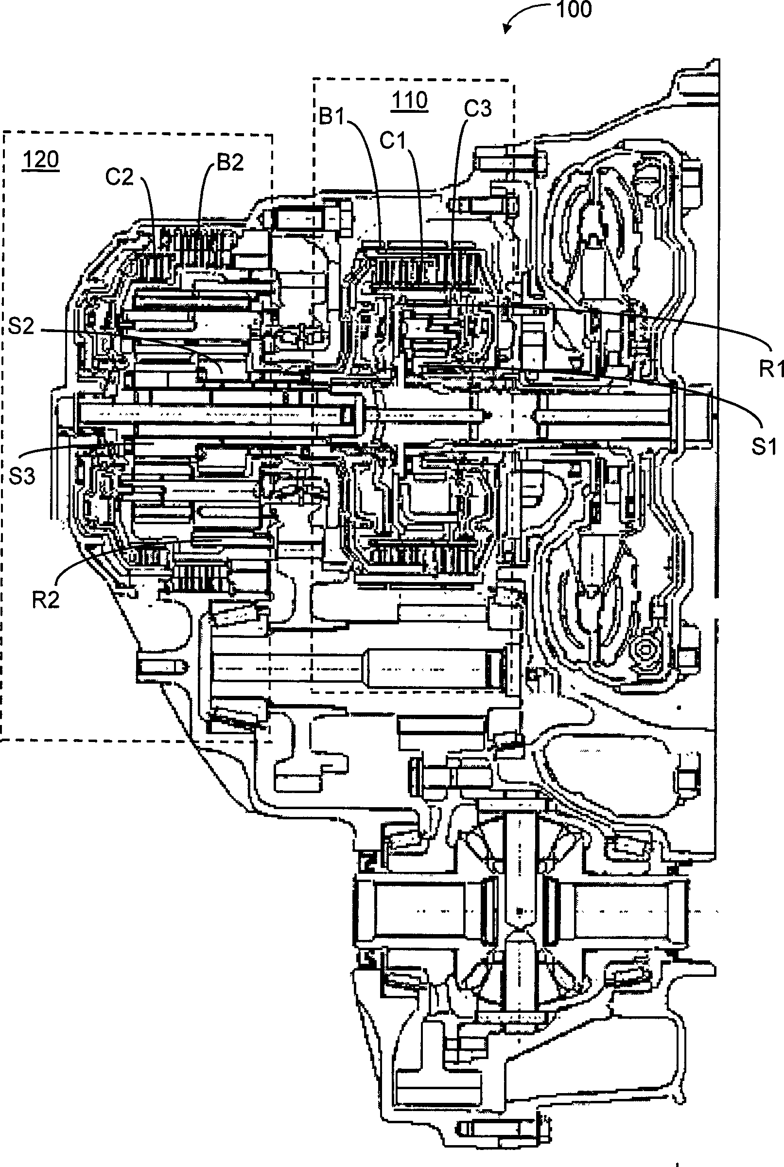
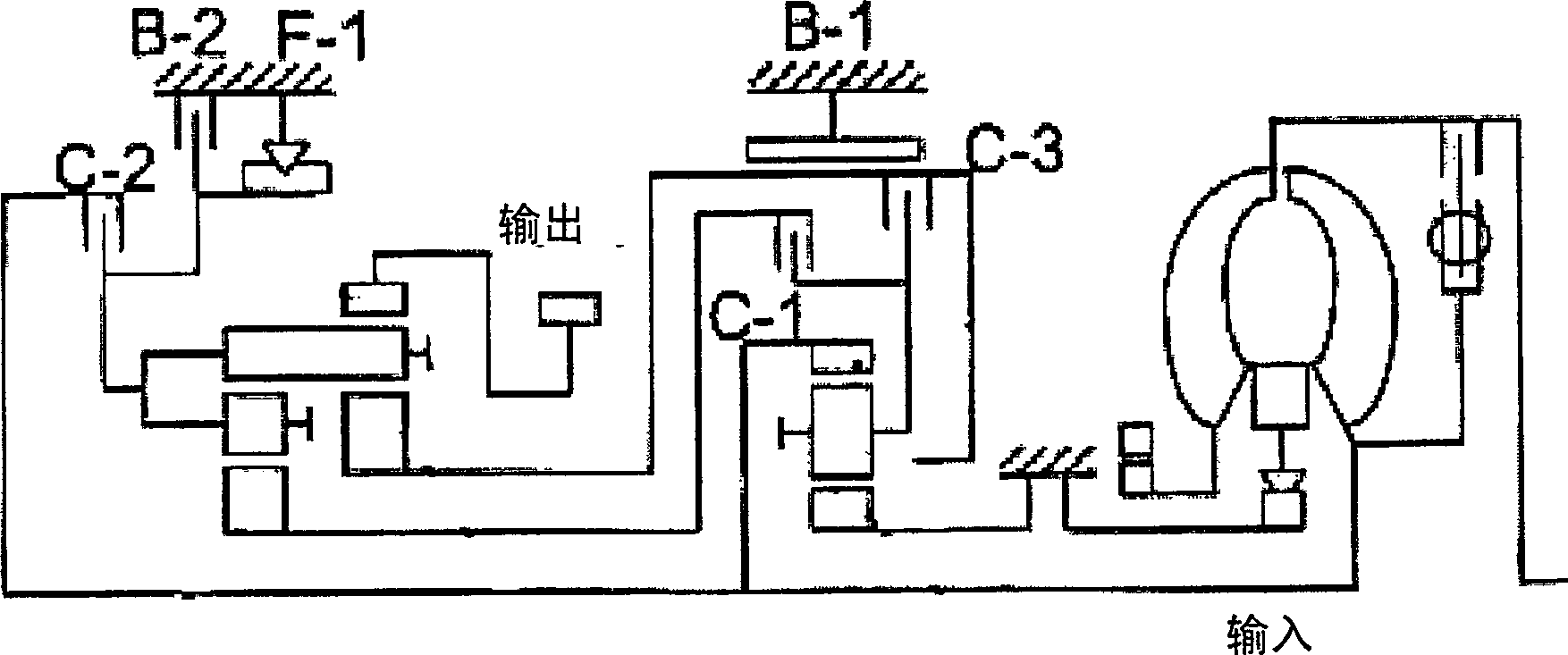
[0025] The method and device for controlling the automatic transmission of the present invention are specifically realized as schematically in figure 1 with figure 2 A six-speed automatic transmission 100 is shown in FIG. 1 , which combines a single-stage planetary gear mechanism 110 with a double-stage planetary gear mechanism or Ravigneaux-type planetary gear mechanism 120 . This existing structure is also referred to as the "Lepe Laijie" type planetary gear mechanism.

[0026] figure 1 A structural sectional view of the transmission is shown here, figure 2 A schematic diagram of a gear mechanism is shown.

[0027] exist figure 1 In the shown structure, the single-stage planetary gear mechanism 110 is used as a reduction transmission or a reduction transmission, and has a sun gear S1, a ring gear R1, planetary gears, and a planetary carrier. The sun gear S1 is permanently fixed. The ring gear R1 is connected to the turbine shaft.

[0028] A double-stage planetary ge...


PUM


Abstract

The invention relates to a method and a device for controlling an automatic transmission, the automatic transmission (100) comprising a single-stage planetary gear train (110) in combination with a two-stage planetary gear train (120), and provision being made for a brake band (B1) assigned to the large sun gear of the two-stage planetary gear train (110) and a brake coupling (B2) assigned to theplanet carrier of the two-stage planetary gear train (120). In order to reduce idling vibrations, the brake band (B1) and the brake coupling (B2) are actuated simultaneously for at least some of the time during an operating state in which the internal combustion engine is idling.

Description

technical field [0001] The present invention relates to a method and apparatus for controlling an automatic transmission. Background technique [0002] Currently in diesel powered vehicles with automatic transmissions it is often necessary to take measures to reduce idle vibration when the automatic transmission is in the "D" ("Drive") position. This is usually done by a control method known as NI or NIC control (NIC stands for "neutral idle control"), where the torque transmitted from the torque converter turbine to the transmission and then to the propshaft is reduced by a slipping input clutch . This clutch is also referred to as the C1 clutch in the so-called "Le Pelletier" six-speed automatic transmission. The slippery C1 clutch allows the turbine to spin at about 90 rpm below the idling speed of the internal combustion engine, reducing the torque converter output torque. The output torque to the axles is thus approximately equal to the product of the engine torque a...

Claims


Application Information

Patent Timeline
Patent Type & Authority Applications(China)
IPC IPC(8): F16H61/20
CPCF16H2057/0012F16H61/0059F16H2061/207F16H61/20
Inventor 马丁·塔尔
Owner FORD GLOBAL TECH LLC
Learn More