
Electromagnetical ultrasonic thickness-measuring method

An electromagnetic ultrasonic and permanent magnet technology, applied in the direction of using ultrasonic/sonic/infrasonic waves, measuring devices, instruments, etc., can solve the problems such as the inability of piezoelectric ultrasonic thickness gauges to work, the inability to detect rough surface materials, and the limitation of application fields.

Inactive Publication Date: 2009-04-01
TSINGHUA UNIV
View PDF2 Cites 56 Cited by
  • Summary
  • Abstract
  • Description
  • Claims
  • Application Information

AI Technical Summary

Problems solved by technology

However, the piezoelectric ultrasonic thickness gauge needs to pass the coupling medium (water, glycerin, etc.) to transmit the ultrasonic wave from the piezoelectric ultrasonic transducer to the material under test, which is inconvenient to use
In addition, due to the need for the transducer to be in contact with the material to be tested, its application fields are also limited. For example, piezoelectric ultrasonic thickness gauges cannot work in high temperature environments (hot steel plate flaw detection above 500 degrees), and cannot detect rough surface materials, etc.

Method used


Image

  • Electromagnetical ultrasonic thickness-measuring method
  • Electromagnetical ultrasonic thickness-measuring method
  • Electromagnetical ultrasonic thickness-measuring method

Examples


Embodiment Construction

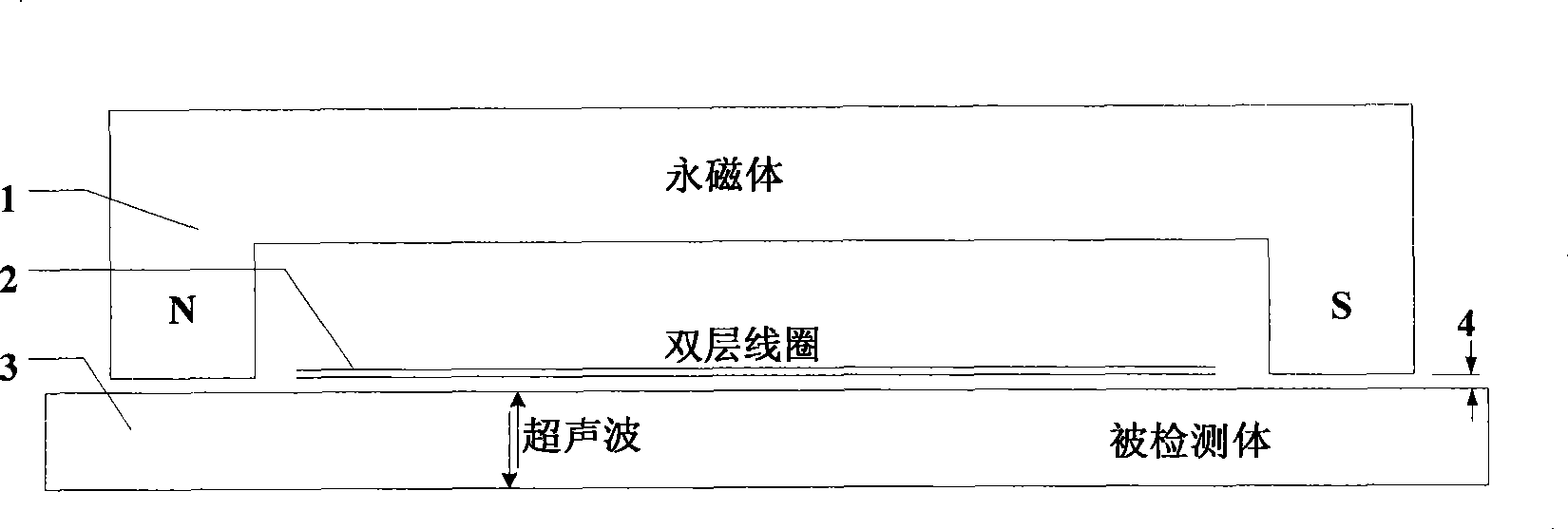
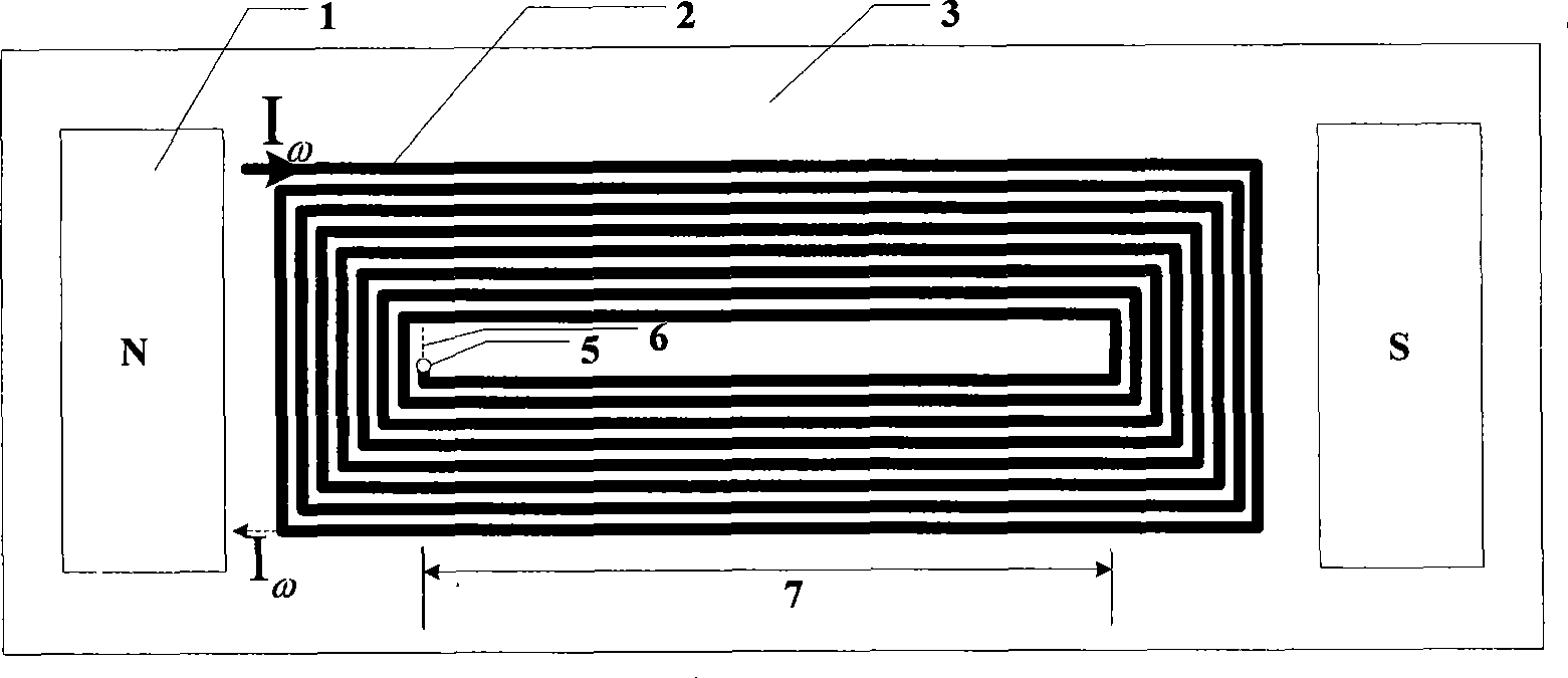
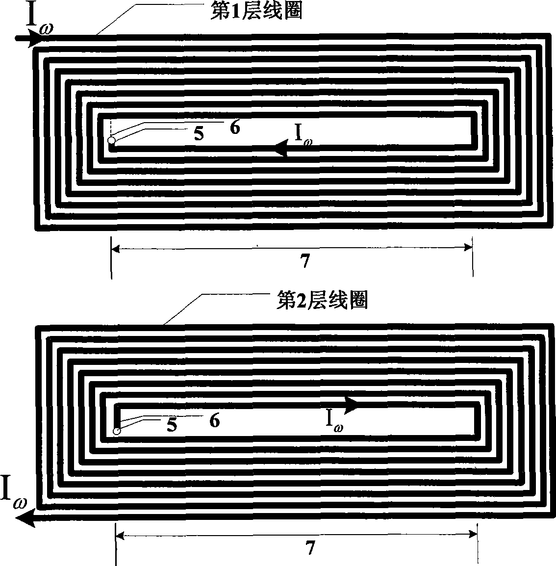
[0018] In the present invention, the electromagnetic ultrasonic transducer is designed based on the principle of magnetostriction, the magnet is a U-shaped NdFeB permanent magnet, and the coil is a "back" double-layer coil. The U-shaped permanent magnet is 40mm-70mm long, 30mm-50mm wide, and 10mm-20mm high; the coil is 30mm-60mm long, 20mm-40mm wide, and the total thickness is 0.3mm-1.5mm. The U-shaped permanent magnet is placed on the object to be tested, and the lift-off height is 0.5mm-1mm, and the magnetic induction intensity of the bias magnetic field generated in the object to be tested is 0.5T-1T. In order to improve the conversion efficiency of the electromagnetic ultrasonic transducer, a double-layer coil is designed to excite and receive ultrasonic waves. The horizontal positions of the upper and lower coils are the same, so that the current direction of the wire at the same position of the first layer and the second layer coil is the same. Such as image 3 As shown...


PUM


Abstract

The invention discloses a method for detecting ferrous magnetic material thickness by utilizing electromagnetic ultrasound, and is characterized in that a magnet inside an electromagnetic ultrasound transducer takes a U-shaped permanent magnet, a coil takes a PCB double-layer coil that takes the shape of a Chinese character, 'Hui' and is positioned at an opening of the permanent magnet, and an effective lead part of the coil is parallel to the direction of a bias magnetic field. In thickness measurement, the electromagnetic ultrasound transducer is positioned on a detected object, high-frequency electric sinusoidal pulse current passes through the coil, according to the magnetostrictive effect, the detected object generates partial stretching deformation and oscillation, and consequently excites ultrasonic transverse wave and leads the ultrasonic transverse wave to spread downwards in a direction vertical to surfaces of the detected object. The ultrasonic wave is reflected by a lower surface of the detected object, and then the reflected wave is received by the coil. A received ultrasonic signal is collected and input into a computer after being amplified. If the ultrasonic wave spreading velocity in the detected object is v, and the spreading time is t, then the thickness of the detected object d is equal to a half of v multiplied by t. The method for detecting ferrous magnetic material thickness by realizing the thickness detection of ferrous magnetic materials, has the non-contact and couplant-free advantages, and can be used in high-temperature environment and for detecting materials with rough surfaces.

Description

technical field [0001] The invention relates to a method for measuring the thickness of a material by using an electromagnetic ultrasonic transducer, which is used for detecting the thickness change and corrosion defects of ferromagnetic materials. Background technique [0002] Steel is prone to defects such as slag inclusions and air bubbles during the production process, and various defects will also appear due to the influence of corrosion, stress and other factors during use. Steel products (such as steel pipes, steel containers) are prone to rupture at defects, causing huge economic losses and casualties. Therefore, it is necessary to effectively detect corrosion pits, uneven thickness and other defects of steel products, and take timely remedial measures. [0003] The most commonly used method is to detect corrosion pits and wall thickness changes by detecting the thickness of the material. At present, the commonly used testing equipment is piezoelectric ultrasonic th...

Claims


Application Information

Patent Timeline
Patent Type & Authority Applications(China)
IPC IPC(8): G01B17/02
Inventor 黄松岭赵伟叶朝峰王珅张永生郝宽胜
Owner TSINGHUA UNIV
Learn More