Microphone circuit

A microphone and circuit technology, applied in the field of microphones, can solve the problems of difficult semiconductor process manufacturing, large chip area, occupation, etc.

Inactive Publication Date: 2009-04-01
FORTEMEDIA
View PDF0 Cites 25 Cited by
  • Summary
  • Abstract
  • Description
  • Claims
  • Application Information

AI Technical Summary

Problems solved by technology

However, 1Ω resistors occupy a large chip area and are difficult to manufacture in semiconductor processes

Method used


Image

  • Microphone circuit
  • Microphone circuit
  • Microphone circuit

Examples


Embodiment Construction

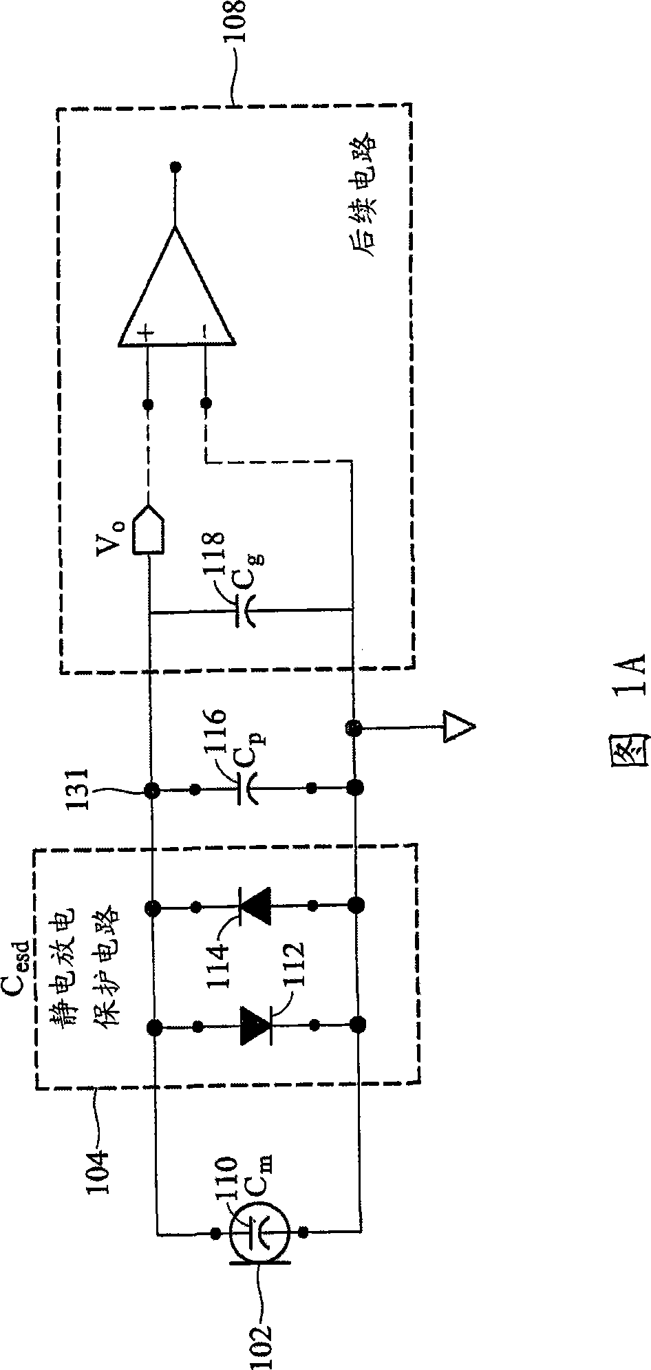
[0066] Fig. 3 prevents the output voltage V according to the present invention o Block diagram of microphone circuit 300 attenuated by parasitic capacitance. The microphone circuit 300 includes a microphone 302 , an ESD protection circuit 304 , a charge amplifier 306 , and a subsequent circuit 308 . The microphone 302 is coupled between the node 331 and the ground potential, and generates a voltage V at the node 331 according to the sound wave i . In one embodiment, the microphone 302 is an electret condenser microphone (ECM). The ESD protection circuit 304 includes two diodes 312 and 314 connected in antiparallel between the node 331 and the ground potential. The output voltage of the microphone 302 V i Mainly by the capacitance C of the microphone capacitor 310 m Decide. Other capacitors coupled between the node 331 and the ground potential include the capacitor C of the ESD protection circuit 304 esd with a capacitance value C p The parasitic capacitance 316.

[00...


PUM


Abstract

The invention provides a microphone circuit. In one embodiment, the microphone circuit comprises a microphone, a self-biased amplifier with a finite gain, and a feedback capacitor. The microphone coupled between a ground and a first node generates a first voltage at the first node according to sound pressure. The self-biased amplifier has a positive input terminal coupled to the ground and a negative input terminal coupled to the first node and amplifies the first voltage according to the finite gain to generate a second voltage at a second node. The feedback capacitor coupled between the first node and the second node feeds back the second voltage to the first node. The second voltage is then output to a following module subsequent to the microphone circuit.

Description

technical field [0001] The present invention relates to microphones, and more particularly to microphone circuits. Background technique [0002] FIG. 1A is a block diagram of a conventional microphone circuit 100 . The microphone circuit 100 includes a microphone 102 , an electrostatic discharge protection circuit 104 , and a follow-up circuit 108 . Microphone 102 detects external sound waves and converts the sound waves into a voltage signal V o , the voltage signal V o It is output to the subsequent circuit 108 at node 131 . In one embodiment, the subsequent circuit 108 is a clamp amplifier or an analog-to-digital converter. The ESD protection circuit 104 includes two diodes 112 and 114 connected in opposite phase, and clamps the voltage signal V o The range of is within a certain limit, so as to protect the subsequent circuit 108 from the impact of electrostatic discharge. [0003] Microphone 102 includes two conductive plates, which form a capacitance value C m of...

Claims


Application Information

Patent Timeline
Patent Type & Authority Applications(China)
IPC IPC(8): H04R3/00H03F3/50
CPCH03F3/187H04R3/00H03F3/70
Inventor 许伟展吴立德魏彦明
Owner FORTEMEDIA
Why Eureka
Try Eureka