Tool change device with a direct drive reciprocating and pivoting actuator

一种换刀装置、驱动装置的技术,应用在工具更换装置、机电装置、喂食装置等方向,能够解决高磨损、低可用性等问题,达到高机械刚性和驱动刚性、提高动态特性和动态抗干扰性的效果

Inactive Publication Date: 2009-04-08
SIEMENS AG
View PDF1 Cites 3 Cited by
  • Summary
  • Abstract
  • Description
  • Claims
  • Application Information

AI Technical Summary

Problems solved by technology

But with conventional technology, the high demands on dynamic performance necessarily lead to high wear and thus low availability

Method used


Image

  • Tool change device with a direct drive reciprocating and pivoting actuator
  • Tool change device with a direct drive reciprocating and pivoting actuator
  • Tool change device with a direct drive reciprocating and pivoting actuator

Examples


Embodiment Construction

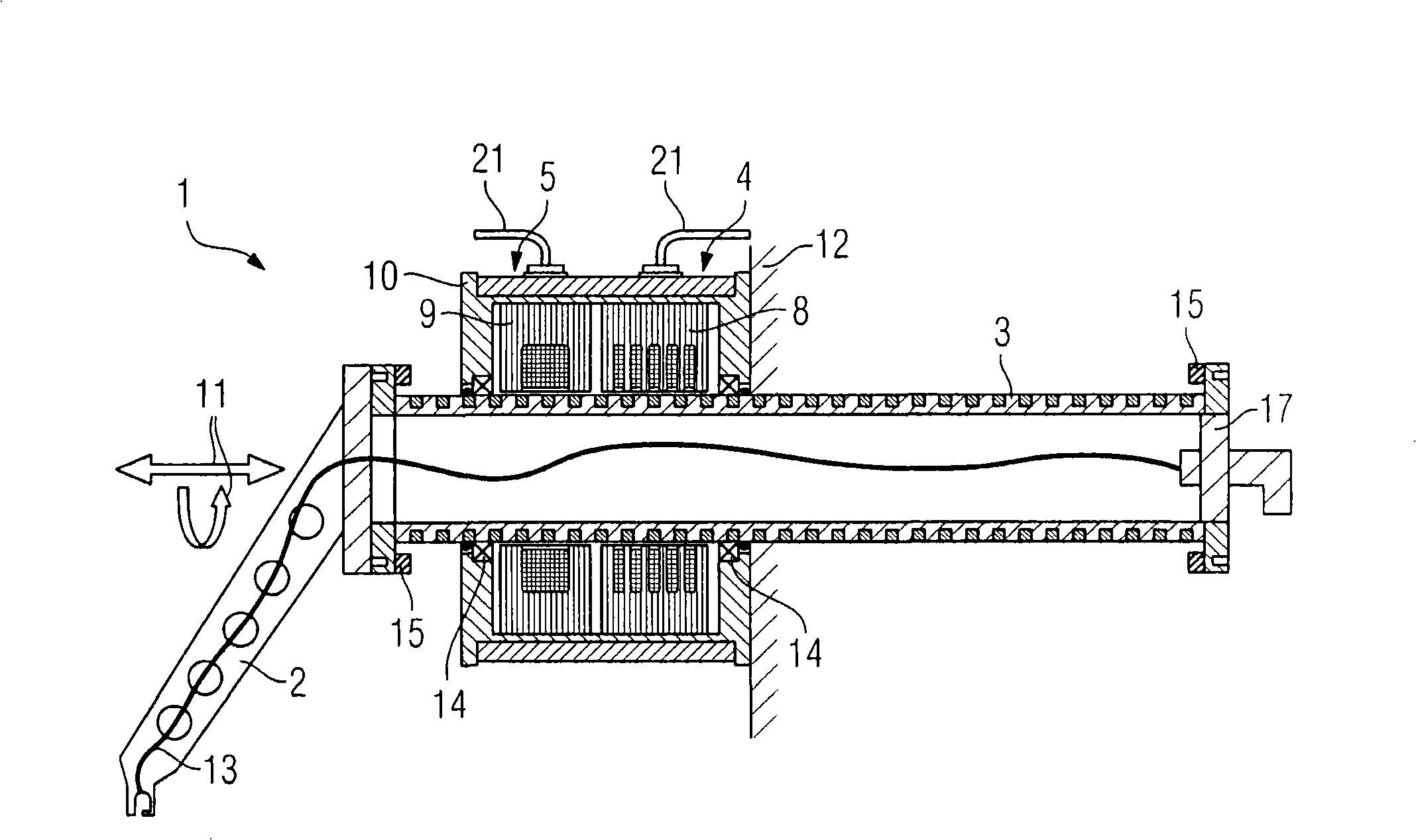
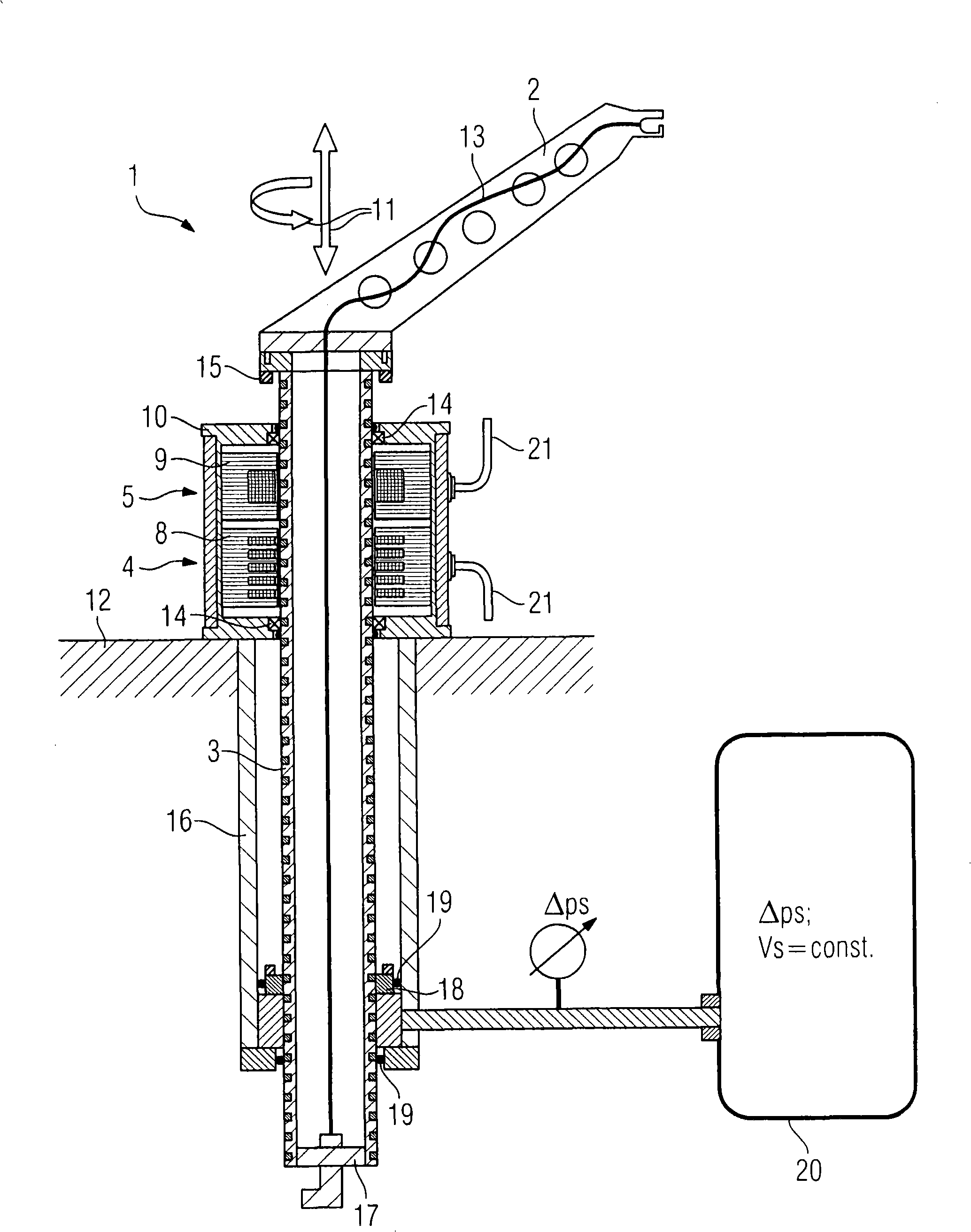
[0032] figure 1 A first embodiment of the tool changing device 1 according to the invention is shown. The tool changing device has a tool changing robot 2 and a lifting and swiveling actuator 3 for carrying out the lifting and swiveling movements. The lifting and swivel actuator 3 can be driven by means of two direct drives 4, 5, wherein the first direct drive 4 is used to generate a linear movement (lifting movement) and the second direct drive 5 is used to generate a rotary movement (swivel movement). sports). The direction of movement of the lifting and pivoting actuator 3 is indicated by arrow 11 . The lifting and pivoting actuator 3 is designed in such a way that it can be rotated through more than 360°, eg multiple turns around its own axis.

[0033] The first direct drive 4 is designed as a solenoid linear motor, that is to say a linear motor with a solenoid coil, which is also referred to as an annular or cylindrical coil. According to its working principle and mod...


PUM


Abstract

The device (1) has a tool gripper (2), and a lifting and pivoting actuator (3) that is drivable with a direct drive (4) e.g. linear motor, for generation of linear motion and another direct drive (5) for generation of rotational motion. The direct drives (4, 5) have a common rotor that serves as the lifting and pivoting actuator.

Description

technical field [0001] The invention relates to a tool changing device with a tool changing robot and a lifting and swiveling actuator, which can be driven by a first direct drive for generating a linear movement and by a second linear drive for generating a rotary movement. Background technique [0002] Tool changers, also known as tool changers, are designed to change tools on machining centres, machine tools or production machines. A tool changer is a mechanical device for automatically changing tools or process-dependent auxiliary devices, such as measuring probes, manipulators or plug gauges (Messdorn), in which the tool is changed from the tool magazine to the machining spindle or In similar devices, vice versa. The change process is carried out, for example, with a single or double robot, wherein the tool change time has a direct influence on the machining time of the machining center. [0003] The tool change is basically carried out by a combination of a lifting m...

Claims


Application Information

Patent Timeline
Patent Type & Authority Applications(China)
IPC IPC(8): B23Q3/155
CPCB23Q5/28B23Q1/4876H02K21/145H02K2201/18H02K41/03B23Q3/1554Y10T483/1755Y10T483/1767Y10T483/19B23Q2003/155407B23Q2003/155411
Inventor 泽利科·贾杰蒂克马克西米利安·克劳斯
Owner SIEMENS AG
Why Eureka
Try Eureka