
Chemical vapor deposition reactor and chemical vapor deposition method

A technology of chemical vapor deposition and reactor, applied in gaseous chemical plating, metal material coating process, coating, etc., can solve problems such as poor reproducibility and consistency, complicated control process, and low chemical vapor reaction efficiency

Active Publication Date: 2009-04-08
李刚
View PDF0 Cites 9 Cited by
  • Summary
  • Abstract
  • Description
  • Claims
  • Application Information

AI Technical Summary

Problems solved by technology

The accumulated deposits on the lateral side walls in the rectangular reaction chamber not only reduce the efficiency of chemical vapor deposition but also have unpredictable effects on the vapor deposition process
Lateral sidewall and vertical reactant depletion effects limit the size of the rectangular chamber and improve the uniformity of the deposited layer
[0014] Obviously, the existing chemical vapor deposition reactors have essential defects, such as the lack of rigid support in the reaction chamber, the complex roof structure, etc., which cannot meet the needs of industrial production, and the expansion of the size of the reaction chamber is also limited by the structure and cost. The upper limit, the gas phase reaction and heat convection and the depletion effect of the reactant along the gas flow direction, the gas flow divergence effect, and the reaction chamber side wall effect all make the chemical vapor phase reaction efficiency in the reaction chamber of the chemical vapor deposition reactor Low, deposition repeatability, reproducibility and consistency are poor, and at the same time, it faces the disadvantages of complex structure of various accessories, high manufacturing and use costs, difficult maintenance and repair, complicated control process, etc.

Method used


Image

  • Chemical vapor deposition reactor and chemical vapor deposition method
  • Chemical vapor deposition reactor and chemical vapor deposition method
  • Chemical vapor deposition reactor and chemical vapor deposition method

Examples


Embodiment approach

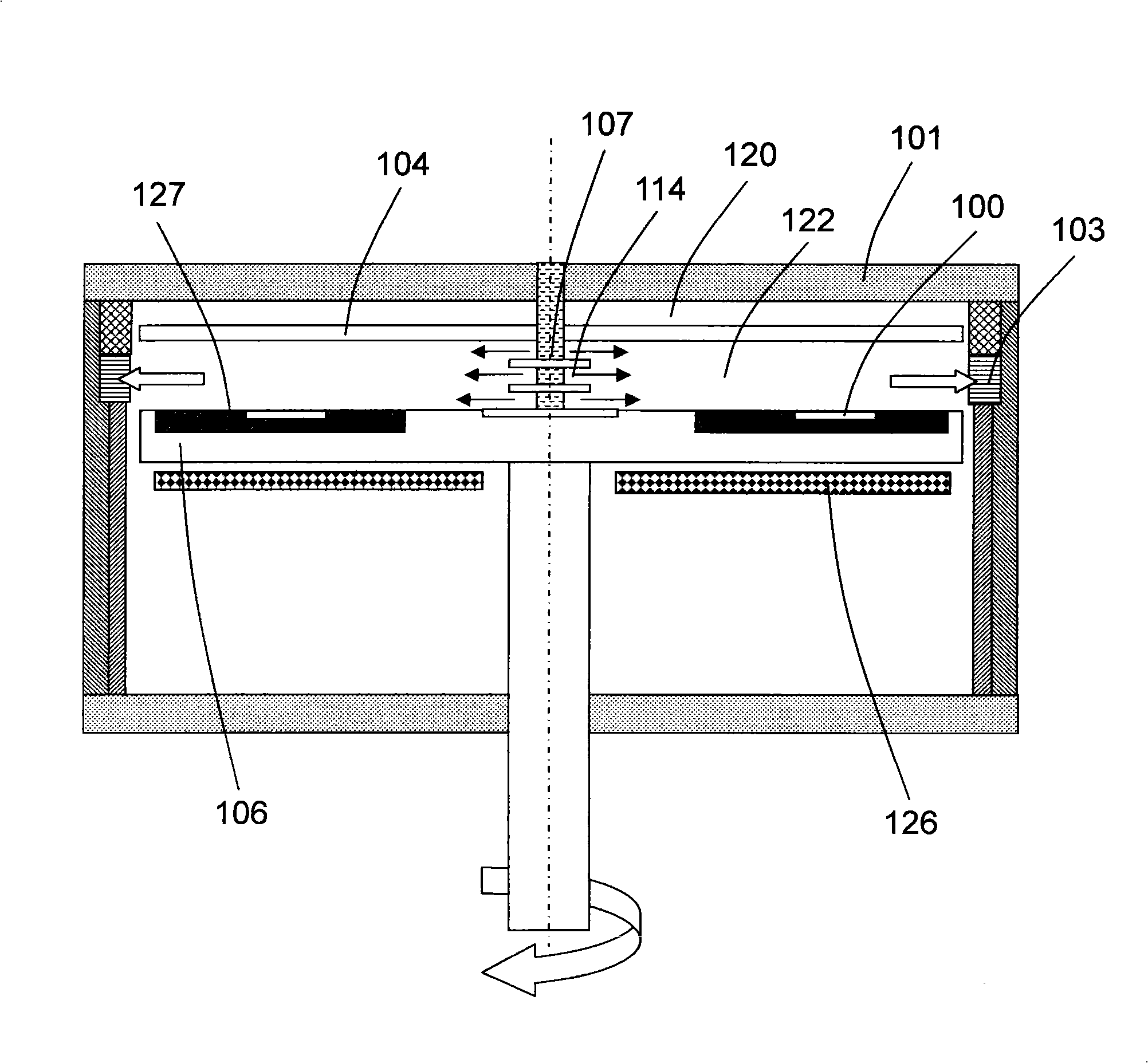
[0031] According to one embodiment of the present invention, a chemical vapor deposition reactor generally has a cylindrical reaction chamber 522 (see Figure 5 ). The cylindrical reaction chamber 522 has a reaction chamber top cover 501, a reaction chamber chassis 513, a cylindrical reaction chamber side wall 511, a cylindrical top cover support 502, an annular substrate carrier 506, A substrate carrier supporting round tubes 540a and 540b, a gas introduction ring 507, an annular gas discharge channel 503b, a heating device 526 placed under the annular substrate carrier, and a The exhaust hole 509 near the chassis of the reaction chamber.

[0032] The cylindrical top cover support 502 is generally placed at the center of the reaction chamber chassis 513, and the centers of the cylindrical top cover support 502 and the cylindrical reaction chamber 522 are usually coincident (concentric circle placement). The top of the cylindrical top cover support 502 is supported to the ce...


PUM


Abstract

The invention discloses a reactor used for chemical vapor deposition and a method for using the reactor to carry out the chemical vapor deposition. The reactor is provided with a cylindrical reaction chamber, the interior of which is provided with a cylindrical top cover support and an annular gas diffusion disk. The cylindrical reaction chamber can realize that multi-stranded gas streams and another gas stream enter the reaction chamber, wherein, the multi-stranded gas streams are along the radial direction which is parallel to a substrate or forms an angle with the surface of the substrate and another gas stream is along the direction vertical to the surface of the substrate. The reaction chamber has the advantages of simple structure, convenient operation and maintenance and low manufacturing and usage costs, and the like, and the using of the reactor for chemical vapor deposition has the advantages of high efficiency, less consumption of sources and good repetition, repeatability, consistency, and the like.

Description

technical field [0001] The present invention mainly relates to a reactor for chemical vapor deposition and a method for chemical vapor deposition using the reactor, and further refers to that the chemical vapor deposition reactor includes a A cylindrical reaction chamber for depositing (also known as epitaxy) single-layer or multi-layer crystalline or amorphous structure on the surface of a crystalline or amorphous substrate. A cylindrical top cover support and an annular gas diffusion plate included in the cylindrical reaction chamber can simplify the design and structure of a large-scale chemical vapor deposition reactor, and reduce the cost of manufacturing and using the large-scale chemical vapor deposition reactor. The cylindrical reaction chamber enables multiple airflows to enter the reaction chamber along a radial direction parallel to the substrate surface or at a certain angle to the substrate surface and another airflow along a direction perpendicular to the substra...

Claims


Application Information

Patent Timeline
Patent Type & Authority Applications(China)
IPC IPC(8): C23C16/455
Inventor 李刚
Owner 李刚
Learn More