

Piston ring of reciprocating engine
A technology of reciprocating motion and piston rings, which is applied in the field of piston rings, and can solve the problems of increased pollution on the inner surface of piston rings, increased blow-by gas volume, etc.
- Summary
- Abstract
- Description
- Claims
- Application Information
AI Technical Summary
Problems solved by technology
Method used
Image


Examples
Embodiment Construction
[0028] Next, the present invention will be described in detail using the embodiments shown in the drawings. However, unless there is a specific description about the dimensions, materials, shapes, relative arrangement, etc. of the components described in this embodiment, they are merely illustrative examples and should not limit the scope of the present invention.
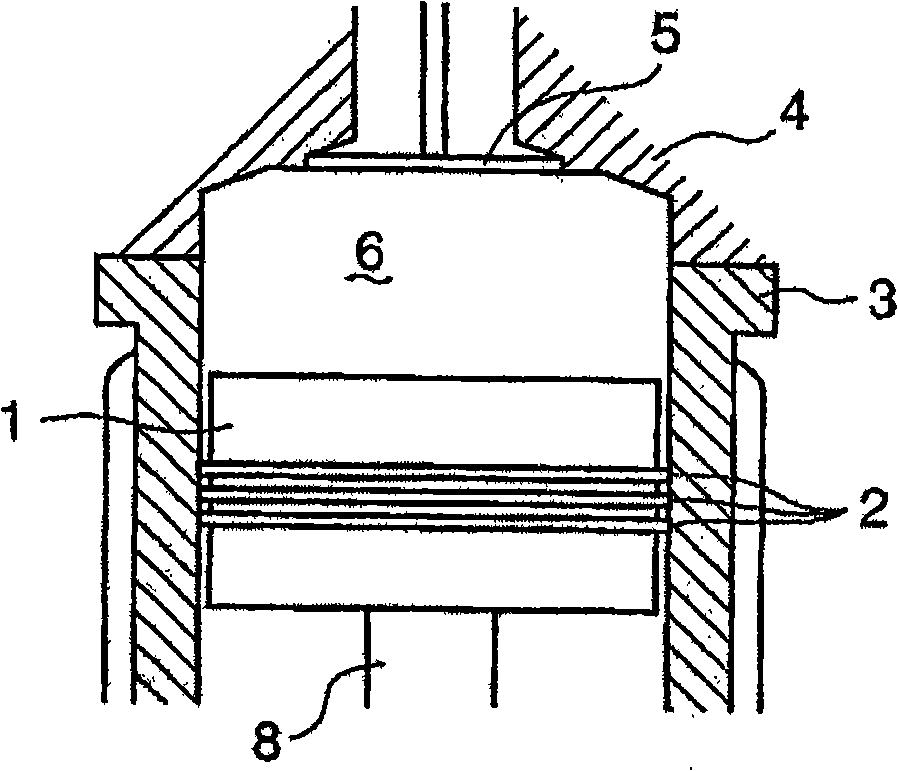
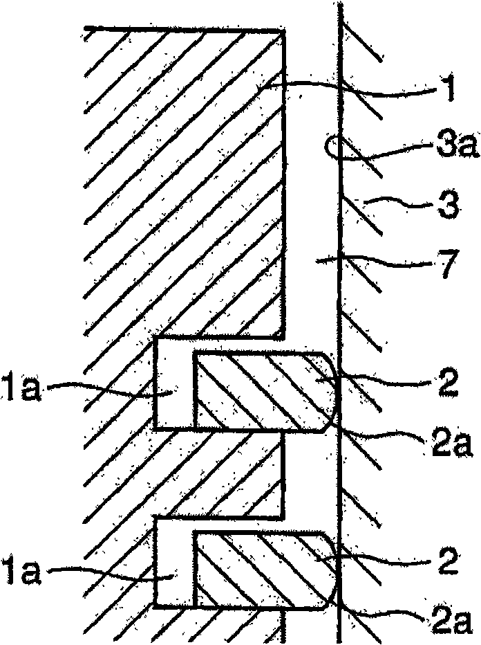
[0029] FIG. 2(A) is a schematic cross-sectional view around a combustion chamber of a large diesel internal combustion engine, and FIG. 2(B) is a partial cross-sectional view near a piston ring mounting portion. In FIG. 2, a plurality of piston rings 2 are respectively inserted into ring grooves 1a formed in the height direction of the piston 1, and the piston 1 reciprocates while slidingly contacting the sliding surface 3a of the cylinder liner 3 with the outer peripheral surface 2a of the piston ring 2. sports. A ring side gap 7 opening to the engine combustion chamber 6 is formed on the upper portion of the pis...
PUM
 Abstract
Description
Claims
Application Information