High-temperature high-pressure difference pressure-reducing valve

A high-temperature, high-pressure, pressure-reducing valve technology, which is applied in the field of pressure-reducing valves, can solve problems such as unsuitable solid particles, small orifice holes, dead angles in pipelines, etc., and achieve the effects of simple structure, reduced erosion and wear, and extended service life

Inactive Publication Date: 2009-04-08
SHANGHAI RES INST OF CHEM IND +2
View PDF3 Cites 12 Cited by
  • Summary
  • Abstract
  • Description
  • Claims
  • Application Information

AI Technical Summary

Problems solved by technology

However, its conical decompression device is composed of an orifice on a hollow cone. The orifice is perpendicular to the flow direction of the fluid, and there is a dead angle in the pipeline, and the diameter of the orifice is also small. Liquid is suitable, but the orifice is small and easy to block, so it is not suitable for materials containing solid particles

Method used


Image

  • High-temperature high-pressure difference pressure-reducing valve
  • High-temperature high-pressure difference pressure-reducing valve
  • High-temperature high-pressure difference pressure-reducing valve

Examples


Embodiment 1

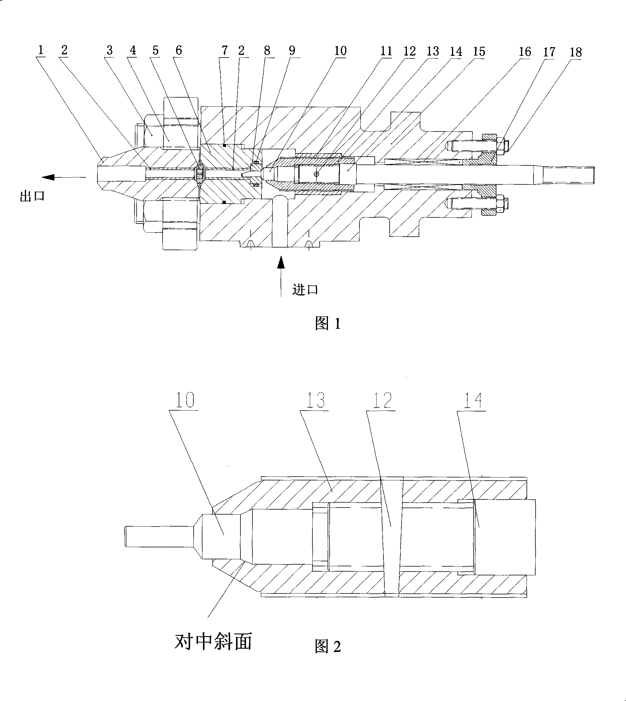
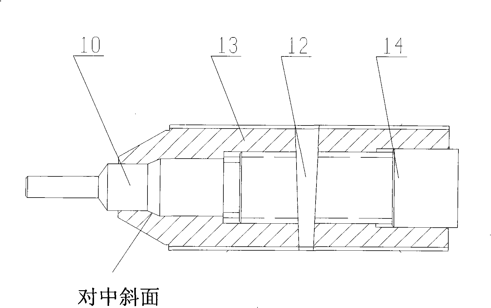
[0032] As shown in Figures 1 to 5, a high-temperature and high-pressure differential pressure reducing valve includes a valve body 15, a valve seat 8, and a valve core 10 that is inside the valve seat 8 and can move up and down within it. The thread and pin 12 are fixedly connected with the valve stem 14, the valve stem 14 is located inside the valve body 15, sealed with the outside world by the sealing packing 16 and the packing gland 17, and can move up and down, the packing gland 17 is connected with the valve body 15 by bolts 18 , The lower part of the valve seat 8 is provided with a bushing 2, a throttle orifice 5, and a flange 4 and a bolt 3 connected to the outside.

[0033] The medium enters the valve cavity from the side, passes through the channel formed by the valve core 10 and the valve seat 8 and the throttle orifice 5 downstream of the valve seat, and then flows out from the outlet body 1 at the tail end. The valve body 15 is the main part, which contains the val...


PUM


Abstract

The invention relates to a high temperature high pressure difference reducing valve, which is characterized in that the reducing valve comprises a valve body, a valve seat, and a valve core which is positioned in the valve seat and can move up and down in the valve seat; the valve core is fixedly connected with a valve rod by a thread and a pin; the valve rod is positioned in the valve body, sealed from the outside world by sealing packing and a packing gland, and can move up and down; the lower part of the valve seat is provided with a bush, a throttle orifice and a flange which is connected with the outer part; and a medium enters into a valve cavity from the side direction, and flows out from the tail end after flowing through a channel composed of the valve core and the valve seat, and the throttle orifice at the downstream of the valve seat,. Compared with the prior art, the high temperature high pressure difference reducing valve can reduce the pressure of materials with high temperature and high solid content, controls the pressure of systems and the liquid position of high-pressure tanks, not only can reduce the pressure and generate required large pressure reduction but also can carry out appropriate flow control; more importantly, the high temperature high pressure difference reducing valve can prevent harsh erosive wear formed by the high-speed flow of medium flow with high solid content under large pressure difference to the materials.

Description

technical field [0001] The invention relates to a pressure reducing valve used in a fluid delivery system, in particular to a pressure reducing valve and a pressure reducing method used in a system with high temperature, high solid content and high pressure drop. Background technique [0002] The pressure reducing valve is a pressure control valve. When the pressure of the hydraulic system reaches the set value of the valve, the pressure reducing valve discharges part or all of the liquid, so as to realize the function of keeping the pressure in the hydraulic system below the set value. [0003] From the point of view of fluid mechanics, the pressure reducing valve is a throttling element that changes the local resistance scientific research, that is, by changing the throttling area, the flow velocity and kinetic energy are changed, resulting in different pressure losses, so as to achieve the purpose of decompression. [0004] The decompression valve described in the patent ...

Claims


Application Information

Patent Timeline
Patent Type & Authority Applications(China)
IPC IPC(8): F16K47/08F16K1/48F16K1/36F16K41/02F16K49/00F16K1/42F16K27/02
Inventor 章序文丁庆华李文博李克健何建铧孙乐申兰建华何平彭东辉王雨
Owner SHANGHAI RES INST OF CHEM IND
Why Eureka
Try Eureka