Micro-oil ignition rotational flow breeze combustion device for preventing slag bonding of primary combustion chamber

A technology of micro-oil ignition and pulverized coal combustion, which is applied to burners, burners, combustion methods and other directions of burning powder fuels, can solve problems such as the amount of ignition oil that is prone to slagging, and is conducive to ignition, full combustion, and combustion. Good effect of stable combustion

Inactive Publication Date: 2010-10-06
HARBIN INST OF TECH
View PDF10 Cites 1 Cited by
  • Summary
  • Abstract
  • Description
  • Claims
  • Application Information

AI Technical Summary

Problems solved by technology

[0004] The purpose of the present invention is to provide a micro-oil ignition swirl pulverized coal combustion device that prevents slagging in the primary combustion chamber, so as to solve the problem of easy generation of slagging in the combustion chamber when the existing micro-oil ignition swirl pulverized coal burner burns. The problem of large ignition fuel consumption under the condition of low load and stable combustion

Method used


Image

  • Micro-oil ignition rotational flow breeze combustion device for preventing slag bonding of primary combustion chamber
  • Micro-oil ignition rotational flow breeze combustion device for preventing slag bonding of primary combustion chamber
  • Micro-oil ignition rotational flow breeze combustion device for preventing slag bonding of primary combustion chamber

Examples


specific Embodiment approach 1

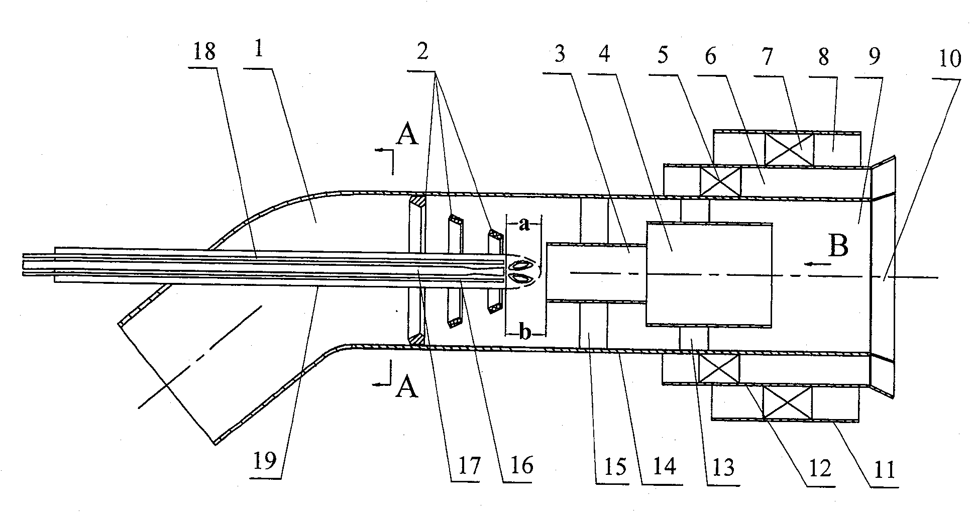
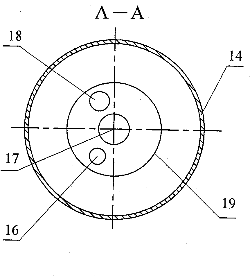
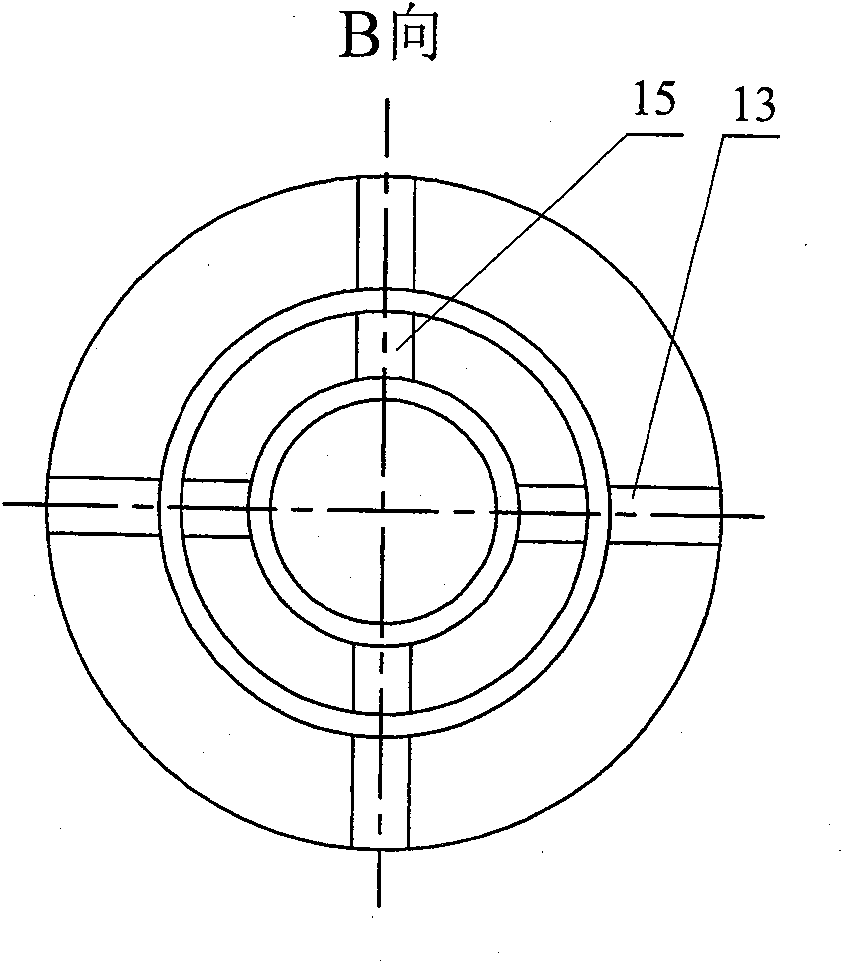
[0008] Specific implementation mode one: combine Figure 1~3 Describe this embodiment. This embodiment includes a primary air duct 1, a concentration ring 2, a primary combustion chamber 3, a secondary combustion chamber 4, an inner swirler 5, an inner secondary air duct 6, and an outer secondary air duct 8. The burner 10, the third air duct pipe 11, the second air duct pipe 12, the first air duct pipe 14 and the main oil gun 17; the combustion device also includes an outer swirler 7, a three-stage combustion chamber 9, The second support plate 13, the first support plate 15 and the casing 19; the primary air duct 1 is inside the first air duct pipe 14, and the outlet end of the first air duct pipe 14 is fixed with a burner 10, and the concentration ring 2 It is fixed in the first air duct pipe 14, and the diameter of the concentration ring 2 gradually decreases along the direction of the concentration ring 2 toward the burner 10. The front end of the sleeve 19 is an open end,...

specific Embodiment approach 2

[0009] Specific implementation mode two: combination figure 1 Describe this embodiment, the difference between this embodiment and specific embodiment one is: the combustion device of this embodiment also includes an auxiliary oil gun 18; one end of the auxiliary oil gun 18 passes through the rear end of the casing 19 and is fixed on the The pipe 19 is arranged parallel to the main oil gun 17 , and the outlet end of the auxiliary oil gun 18 corresponds to the inlet end of the primary combustion chamber 3 . When the flame was unstable, the auxiliary oil gun 18 could be enabled in time to help the pulverized coal to burn.

specific Embodiment approach 3

[0010] Specific implementation mode three: combination figure 1 Describe this embodiment, the difference between this embodiment and the second embodiment is: the combustion device of this embodiment also includes a flame detection tube 16; one end of the flame detection tube 16 passes through the rear end of the sleeve 19 and is fixed on the sleeve In the pipe 19 , the outlet end of the flame detection pipe 16 corresponds to the inlet end of the primary combustion chamber 3 . So set, can detect at any time after main oil gun 17 is ignited, surrounding flame stability, when flame is unstable, can enable auxiliary oil gun 18 in time, helps pulverized coal to burn.

[0011] The working principle is: after the pulverized coal and air sent from the primary air pulverized pipeline flow into the concentration ring 2 in the primary air duct 1, a relatively high concentration of pulverized coal is formed in the central area of ​​the primary air duct 1. In chamber 3, the pulverized co...


PUM


Abstract

The invention discloses a micro-oil ignition swirling pulverized coal burning device for preventing slag formation in a first-class burning chamber, which relates to a swirling pulverized coal burning device for preventing slag formation in a first-class burning chamber, and aims at solving the problems of easy slag formation in the burning chamber during burning and large oil consumption for ignition under low-load stable burning of the existing micro-oil ignition swirling pulverized coal burner. A concentration ring is fixed in a first air channel pipe, a sleeve is fixedly arranged in the concentration ring, the first-class burning chamber and a second-class burning chamber are fixed in the first air channel pipe at the front end of the sleeve, one end of a main oil gun is fixed in the sleeve, a second air channel pipe is fixedly sheathed on the first air channel pipe, an inner swirler is fixed in an inner secondary air channel, a third air channel pipe is fixedly sheathed on the second air channel pipe, an outer swirler is fixed on an outer secondary air channel, the axial distance between the sleeve and the first-class burning chamber is b, a backflow area is generated at the front end of the sleeve, the axial distance between the front border of the backflow area and the mouth of the sleeve is a, and b is more than a. The burning device has the advantages of having no slag formation in the first-class burning chamber during burning and small oil consumption for ignition.

Description

technical field [0001] The invention relates to a swirl pulverized coal combustion device for preventing slagging in a primary combustion chamber. Background technique [0002] Large-scale power plant boilers consume a lot of oil during ignition and low-load stable combustion. In order to save fuel, power generation companies shift the focus of fuel saving from low-load stable combustion to boiler ignition and shutdown (oil consumption accounts for 60% when power plant boilers start and stop. , low-load stable fuel consumption accounts for 40%). Swirl burners occupy a certain proportion in my country's power plant boilers and other pulverized coal applications. The large pulverized coal boiler with swirl burner has its unique advantages: firstly, it can avoid the thermal deviation in the superheater area; secondly, there is no strict requirement on the shape of the furnace. With the development of large-capacity units in my country, there is an urgent requirement for the d...

Claims


Application Information

Patent Timeline
Patent Type & Authority Patents(China)
IPC IPC(8): F23D1/02F23D17/00
Inventor 李争起陈智超赵洋刘春龙
Owner HARBIN INST OF TECH
Why Eureka
Try Eureka