Refrigeration device

A refrigeration device and unit technology, applied in refrigerators, refrigeration components, refrigeration and liquefaction, etc., can solve the problems of reduced reliability of refrigeration devices, reduced refrigerant circulation, and reduced pressure

Inactive Publication Date: 2009-04-08
DAIKIN IND LTD
View PDF1 Cites 2 Cited by
  • Summary
  • Abstract
  • Description
  • Claims
  • Application Information

AI Technical Summary

Problems solved by technology

In addition, it is also considered that if the maintenance valve is damaged due to the moisture expansion, air leakage will occur from the maintenance valve, and as a result, the reliability of the refrigeration unit will be reduced.
[0005] Also, when a maintenance valve is installed on the suction side of the low-stage compressor, the pressure loss on the suction side may increase due to the flow resistance of the valve body itself.
Due to the influence of the increase in pressure loss, the pressure at the compressor suction port (point) decreases, and the refrigerant circulation volume decreases, which may also lead to a decrease in refrigeration capacity.
[0006] Furthermore, when parts need to be replaced not in the booster unit but in the utilization-side unit, in order to recover the refrigerant remaining in the utilization-side heat exchanger and perform maintenance, it is necessary to carry out evacuation work. The maintenance time of the side unit has not been shortened

Method used


Image

  • Refrigeration device
  • Refrigeration device

Examples


Embodiment Construction

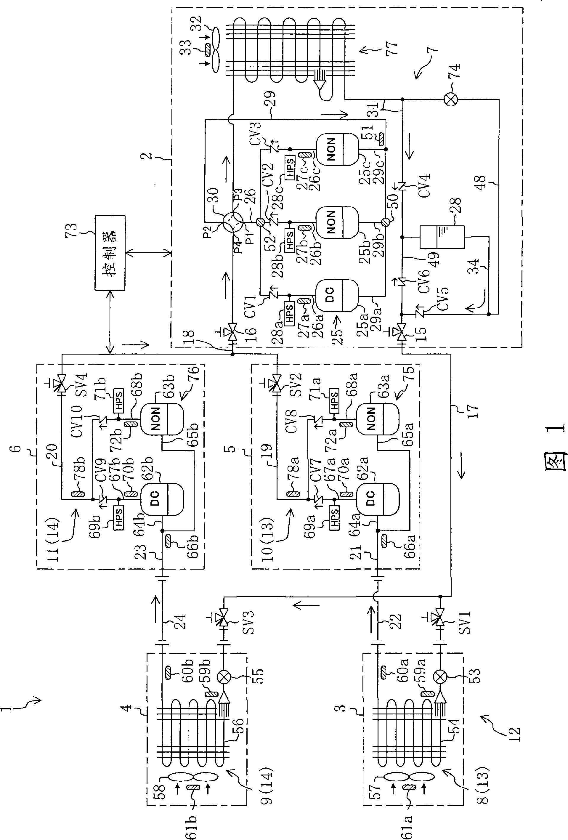
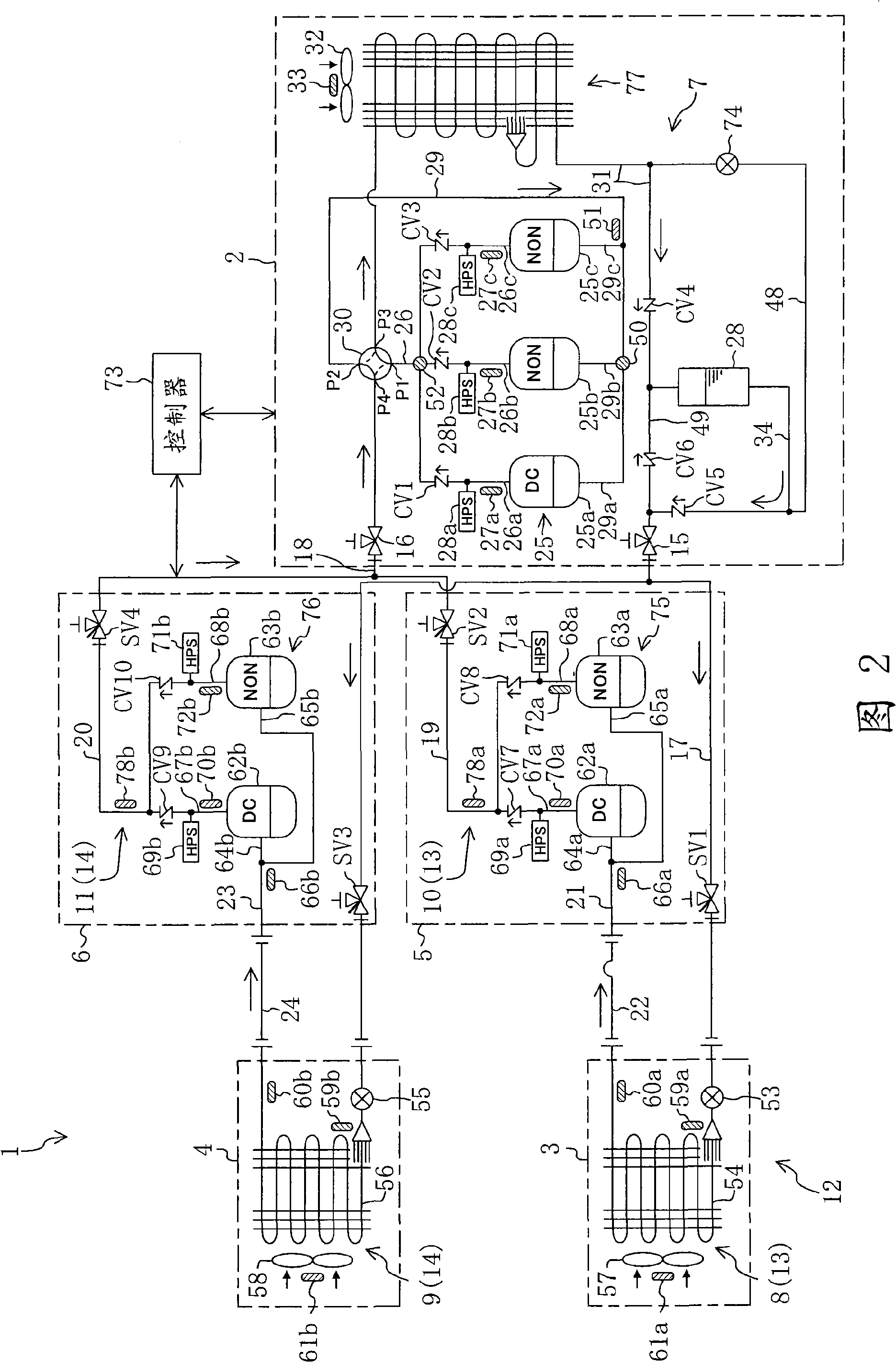
[0026] Embodiments of the present invention will be described in detail below with reference to the drawings.

[0027] This embodiment shown in FIG. 1 relates to the refrigeration apparatus 1 which performs cooling operation in two freezers.

[0028] The freezer 1 has an outdoor unit (heat source side unit) 2 installed outdoors, a first storage unit (first utilization side unit) 3 and a second storage unit (second utilization side unit) installed in the freezer. ) 4, the first booster unit 5 and the second booster unit 6.

[0029] An outdoor circuit 7 having a high-stage compression mechanism 25 and an outdoor heat exchanger (heat source side heat exchanger) 77 is installed in the outdoor unit 2, and an outdoor circuit 7 having a first indoor heat exchanger (the second heat exchanger) is installed in the first indoor unit 3. A first refrigerating circuit 8 using a side heat exchanger) 54, a second refrigerating circuit 9 with a second refrigerated heat exchanger (a second uti...


PUM


Abstract

The present invention discloses a refrigeration device having in-chamber units (3, 4) and booster units (5, 6). First service valves (SV1, SV3) on the first and the second system side are placed in liquid lines each laid between an outdoor heat exchanger (77) and each of in-chamber heat exchangers (54, 56), and second service valves (SV2, SV4) on the first and the second system side are placed on the exit sides of the booster units (5, 6). Maintainability of the in-chamber units (3, 4) and the booster units (5, 6) is improved without impairing reliability and refrigeration ability of the refrigeration device.

Description

technical field [0001] The present invention relates to a refrigerating device with a refrigerant circuit for performing a two-stage compression refrigerating cycle, in particular to a refrigerant recovery mechanism. Background technique [0002] Heretofore, refrigerating apparatuses having a refrigerant circuit performing a two-stage compression refrigeration cycle have been known. In this refrigeration unit, a heat source side unit having a high-stage compressor and a heat source side heat exchanger, a utilization side unit having an expansion mechanism and a utilization side heat exchanger, and a booster unit having a low stage compressor are connected by refrigerant piping. unit) connected. In the refrigerant circuit of this refrigerating device, the intermediate-pressure gaseous refrigerant sucked by the high-stage compressor is compressed to a predetermined high pressure, discharged from the high-stage compressor, and then condensed by dissipating heat in the heat sou...

Claims


Application Information

Patent Timeline
Patent Type & Authority Applications(China)
IPC IPC(8): F25B45/00F25B1/00F25B1/10F25B41/04
CPCF25B45/00Y02B30/741F25B13/00F25B41/003F25B2500/06F25B2313/0233F25B2313/006F25B2600/021F25B2313/02741F25B1/10F25B2400/0751Y02B30/70
Inventor 阪江觉向谷俊昭有井启二
Owner DAIKIN IND LTD
Why Eureka
Try Eureka