
Magnetic resonance elasticity imaging pillow style excited by electromagnetism device

A magnetic resonance elasticity and imaging device technology, applied in the fields of magnetic resonance measurement, diagnosis using vibration, medical science, etc., can solve problems such as limited practical application value, little clinical practical application value, bleeding gums, etc.

Inactive Publication Date: 2009-04-15
高培毅
View PDF0 Cites 6 Cited by
  • Summary
  • Abstract
  • Description
  • Claims
  • Application Information

AI Technical Summary

Problems solved by technology

[0004] The needle-type vibration excitation device uses the electric needle pierced into the body as the excitation device to generate shear waves locally in the tissue; the disadvantage of this method: invasive examination, and can only be used for small-scale local imaging, so the practical application value is limited
The disadvantages are: ①The contact area between the bite-type excitation device and the subject is small, and the oscillatory wave needs to propagate through the contact surface in the subject, so this method is not conducive to the analysis of the image wavelength in MRE examination; ②During MRE examination, the single-level The inspection takes several minutes, and it will take longer if a multi-level inspection is required. For patients, especially those with poor general conditions, it is difficult to achieve long-term locking vibration excitation devices, so this method is of little value in clinical practice. large; ③When the vibration generated by the bite-type excitation device propagates through the teeth, a small number of subjects will experience bleeding gums, and this method has high requirements for the sanitation and disinfection of the excitation device before each inspection, and at the same time, a small number of subjects cannot accept This kind of stimulation device needs to enter the mouth, so that the examination cannot be performed

Method used


Image

  • Magnetic resonance elasticity imaging pillow style excited by electromagnetism device
  • Magnetic resonance elasticity imaging pillow style excited by electromagnetism device
  • Magnetic resonance elasticity imaging pillow style excited by electromagnetism device

Examples


Embodiment Construction

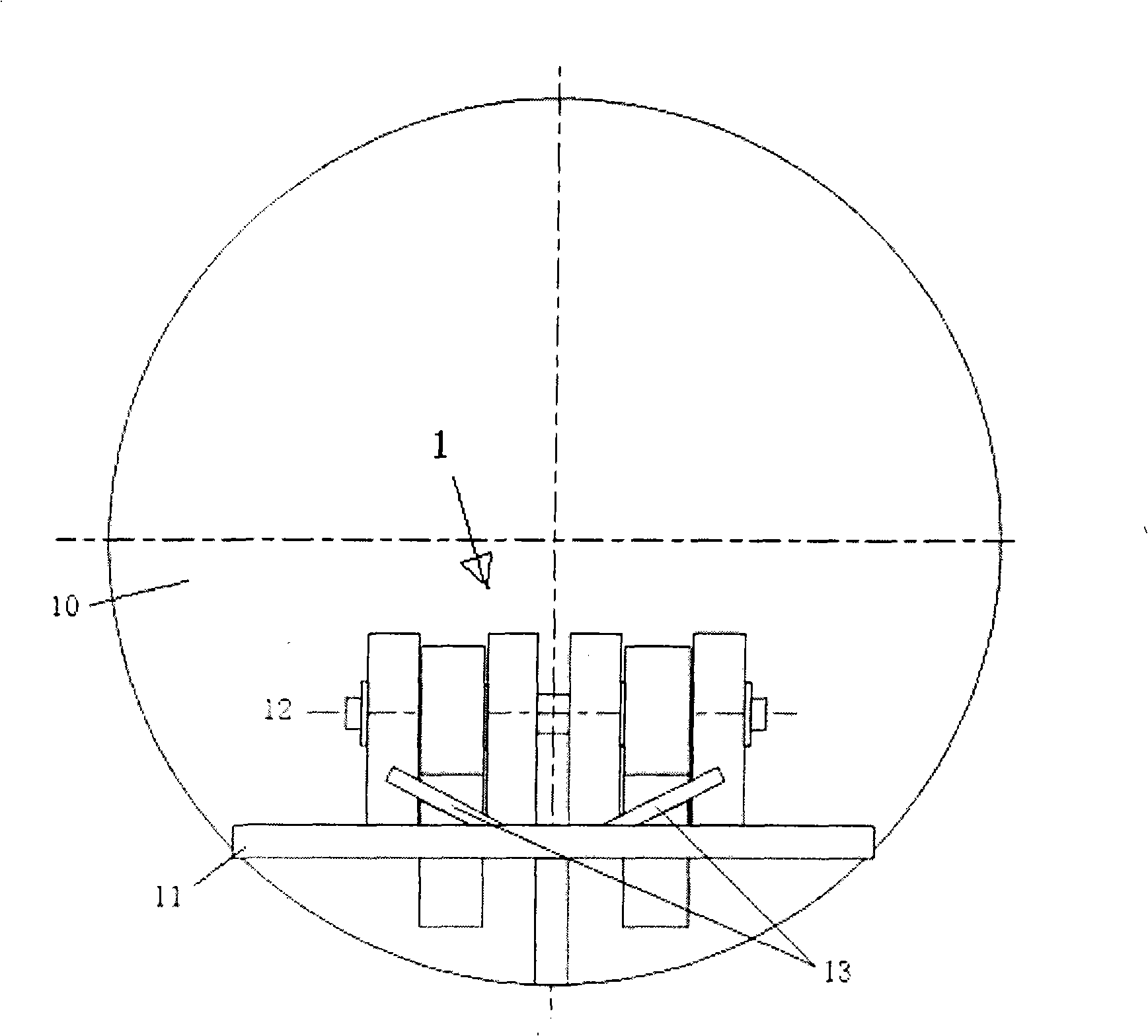
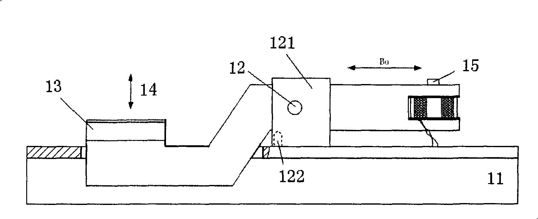
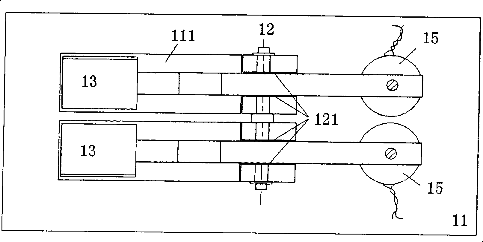
[0030] Such as figure 1 , 2 , 3 and 4, the magnetic resonance elastography head pillow type electromagnetic excitation device 1 is arranged in the magnetic resonance elastography equipment (MRI) 2 detection channels 10, and it includes a platform 11, which is connected below or above the platform 11 The guide rail in the detection channel 10 of the imaging device 2 can move in and out in the detection channel 10 during detection (see figure 1 , 4 ). A support shaft 12 is fixed on the stand 11 through a bearing seat 121, and two drive plates 13 are rotatably arranged on the support shaft 12. The two drive plates 13 are arranged in parallel, and the same An electromagnetic coil 15 is arranged on each end of the end, and the direction of its magnetic field is as follows: figure 2 Shown by the middle arrow Bo. The copper wires on it are connected to the output interface of the low-frequency sinusoidal signal amplifier of the magnetic resonance elastography device, and the ...


PUM


Abstract

The invention discloses a magnetic resonance elastography head pillow-type electromagnetic excitation device, which comprises a table frame; a support shaft is fixed on the table frame; the support shaft can be rotationally provided with at least one driving plate, one end of the driving plate positioned on one side of the support shaft is provided with an electromagnetic coil on which a copper wire is used to be connected with an output interface of a low frequency sinusoidal signal amplifier of the magnetic resonance elastography device, and one end of the driving plate positioned on the other side of the support shaft forms a head pillowing part. The excitation device has the advantages that the excitation device sufficiently considers the clinical practicability, has good comfort, so that a patient is easy to accept; during inspection, the head of an inspected person can be substantially contacted with the vibrational excitation device, so the inspected person has no adverse reaction even if receiving the inspection for a longer period, and the device can complete routine MRI inspection and MRE inspection at one time.

Description

technical field [0001] The invention relates to an external vibration excitation device for magnetic resonance elastography, in particular to a head pillow type electromagnetic excitation device for magnetic resonance elastography. Background technique [0002] Magnetic resonance elastography (Magnetic Resonance Elastography, MRE), as a new non-invasive imaging method that can visually display and quantify tissue elasticity, has shown promising research and clinical application prospects. Especially in the examination of brain tissue, it provides a brand-new inspection method that reflects the biomechanical properties of the tissue, and is currently the only non-invasive method that can measure the elasticity of living brain tissue. The working principle of MRE technology is to add a set of mechanical vibration devices to the magnetic resonance imaging equipment, apply an external force on the surface of the object to generate the displacement of the particle in the medium, ...

Claims


Application Information

Patent Timeline
IPC IPC(8): A61B5/055G01R33/34
CPCA61B5/0051
Inventor 高培毅
Owner 高培毅
Learn More