Crude oil electric desalting test device

A test device and electric desalination technology, applied in the field of crude oil electric desalination test device, can solve the problems of large deviation of test data and production data, lack of guiding significance in production and research, and only static test can be carried out, so as to achieve less time spent and improved Accuracy and reliability, the effect of simple operation

Inactive Publication Date: 2009-04-15
CHINA PETROLEUM & CHEM CORP
View PDF2 Cites 10 Cited by
  • Summary
  • Abstract
  • Description
  • Claims
  • Application Information

AI Technical Summary

Problems solved by technology

Chinese patent ZL91229941.X discloses an electric desalination test instrument, which is composed of an electric desalter, a bath fluid box, a thermal fluid, a heater and an electric control mechanism. The rod-type electrode structure can partially simulate the working condition of electric desalination, but because it cannot continuously feed materials, only static tests can be carried out, so the test data and actual production data deviate greatly, which lacks guiding significance for production and research
Chinese patent ZL02259725.5 discloses an electric desalination test device, which is characterized in that the top of the electric desalination tank adopts a sealed structure, which can ensure that it is completely sealed under certain electric field, temperature, and pressure conditions when simulating industrial electric desalination operations. It does not leak and can realize continuous feeding, but due to the power limitation of the electric control mechanism, the processing scale is too small; when simulating the electric field strength, the test data and production data deviate greatly

Method used


Image

  • Crude oil electric desalting test device
  • Crude oil electric desalting test device
  • Crude oil electric desalting test device

Examples


Embodiment Construction

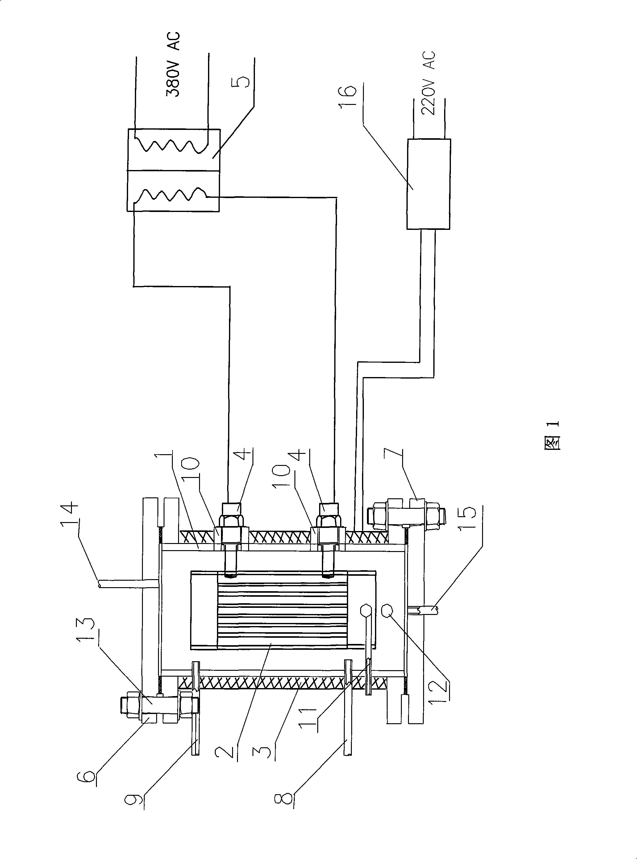
[0009] The present invention will be described in further detail below in conjunction with the accompanying drawings and embodiments.

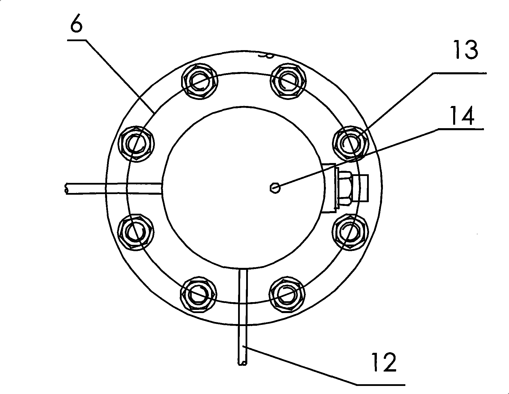
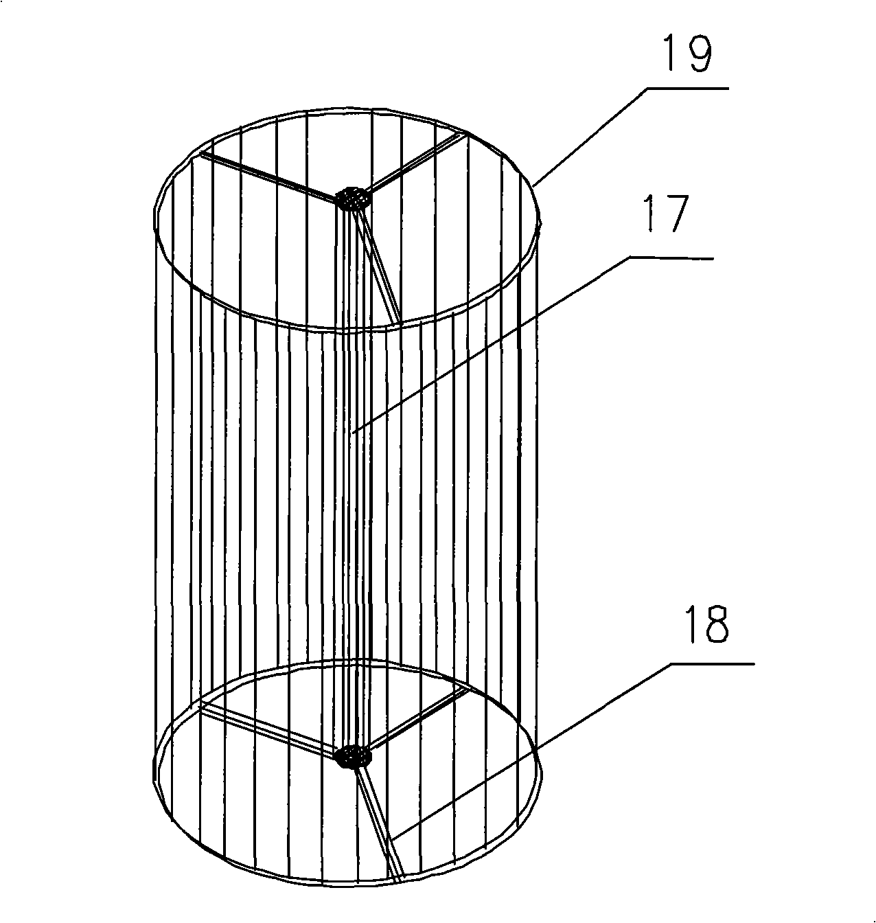
[0010] The present invention has a tank body 1. The inside of the tank body 1 is equipped with an overall cylindrical electrode grid 2, and the outside is equipped with a temperature-controllable electric heating jacket 3. There is an upper sealing flange 6 on the top of the tank body 1, and a lower sealing method on the bottom. Lan 7, there are crude oil inlet pipe 8 and crude oil outlet pipe 9 on the left lower part and left upper part of the tank body 1 respectively, and there are two high-voltage electric inlets 10 on the right part, and a thermometer 11 is inserted into the tank body 1 through the insertion port, and the tank body 1 There is an observation sampling 12 at the front lower part of the tank, and the sample in the tank body 1 can be observed for analysis and control without interrupting the test process. The upper sealing flan...


PUM


Abstract

The invention discloses a test device for crude oil electric desalting, comprising a tank body with upper and lower parts sealed by flanges. A cylindrical electrode grid is arranged inside the tank body and an electric heating sleeve is arranged outside the tank body; an outlet pipe and an inlet pipe of the crude oil as well as a thermometer inserting port are arranged at the upper part of the tank body, while an observing and sampling port and a sewage draining exit are positioned at the lower part of the tank body. The crude oil is fed continuously through the outlet pipe and the inlet pipe, the electric field intensity in the tank body is regulated by a transformer and the temperature of the tank body is controlled by the electric heating sleeve. When researching the conditions of the electric desalting process, the test device can effectively simulate the actual conditions of the electric desalting operations; control the conditions by direct visual measurement through the observing and sampling port in the operation process; and take samples and make analysis without interrupting the test, thus improving the accuracy and reliability of the test. Moreover, with simple operation, shortened test time and repeatability of test results, the test device can be conveniently used in various tests on the desalting effects of the electric desalting devices, and effectively prolong the running period of the refinery equipment.

Description

technical field [0001] The invention relates to a crude oil electric desalting test device, which can be used for simulating and researching the electric desalting device in the petrochemical industry. Background technique [0002] The crude oil electric desalting device is the leading device among many devices in the oil refining industry, and the desalination and dehydration of crude oil is also the first process in the anti-corrosion process of the oil refining process. Chinese patent ZL91229941.X discloses an electric desalination test instrument, which is composed of an electric desalter, a bath fluid box, a thermal fluid, a heater and an electric control mechanism. The rod-type electrode structure can partially simulate the working conditions of electric desalination, but because it cannot feed continuously, only static tests can be carried out, so the test data deviates from the actual production data, which lacks guiding significance for production and research. Chi...

Claims


Application Information

Patent Timeline
Patent Type & Authority Applications(China)
IPC IPC(8): C10G32/02
Inventor 刘小辉李延渊黄贤滨郑俊鹤谢守明
Owner CHINA PETROLEUM & CHEM CORP
Why Eureka
Try Eureka