Method for manufacturing rotor portion of motor integrated type pump and motor integrated type pump equipped with the rotor portion

A manufacturing method and integrated technology, which are applied to components of pumping devices for elastic fluids, manufacturing stator/rotor bodies, non-variable-capacity pumps, etc., can solve problems such as magnet deterioration, improve productivity, improve The effect of production performance, easy arrangement and arrangement

Inactive Publication Date: 2009-04-15
PANASONIC CORP
View PDF1 Cites 6 Cited by
  • Summary
  • Abstract
  • Description
  • Claims
  • Application Information

AI Technical Summary

Problems solved by technology

[0007] However, even in the case where the above-mentioned exposed portion is blocked with other parts (such as a front cover), since deterioration occurs over time, a slight gap is g

Method used


Image

  • Method for manufacturing rotor portion of motor integrated type pump and motor integrated type pump equipped with the rotor portion
  • Method for manufacturing rotor portion of motor integrated type pump and motor integrated type pump equipped with the rotor portion
  • Method for manufacturing rotor portion of motor integrated type pump and motor integrated type pump equipped with the rotor portion

Examples


Example Embodiment

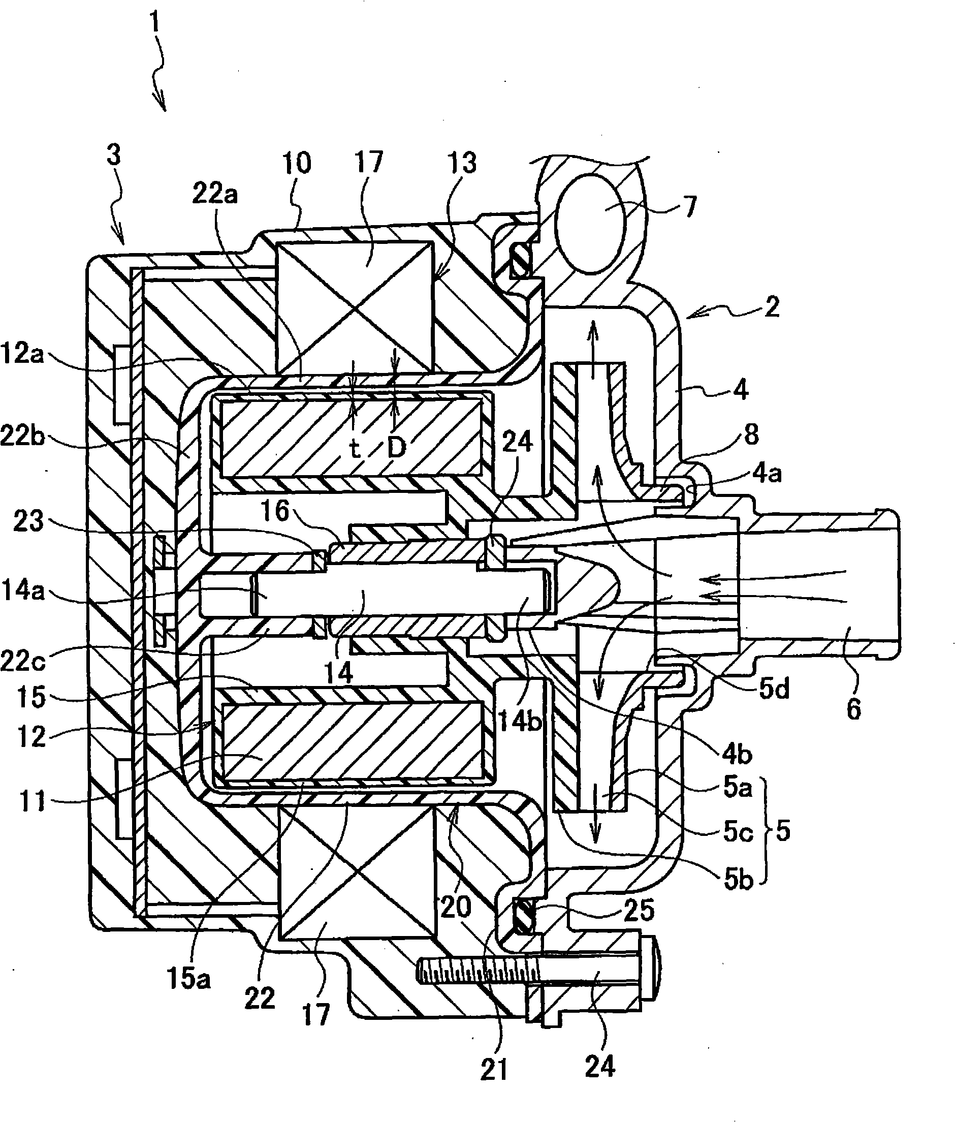
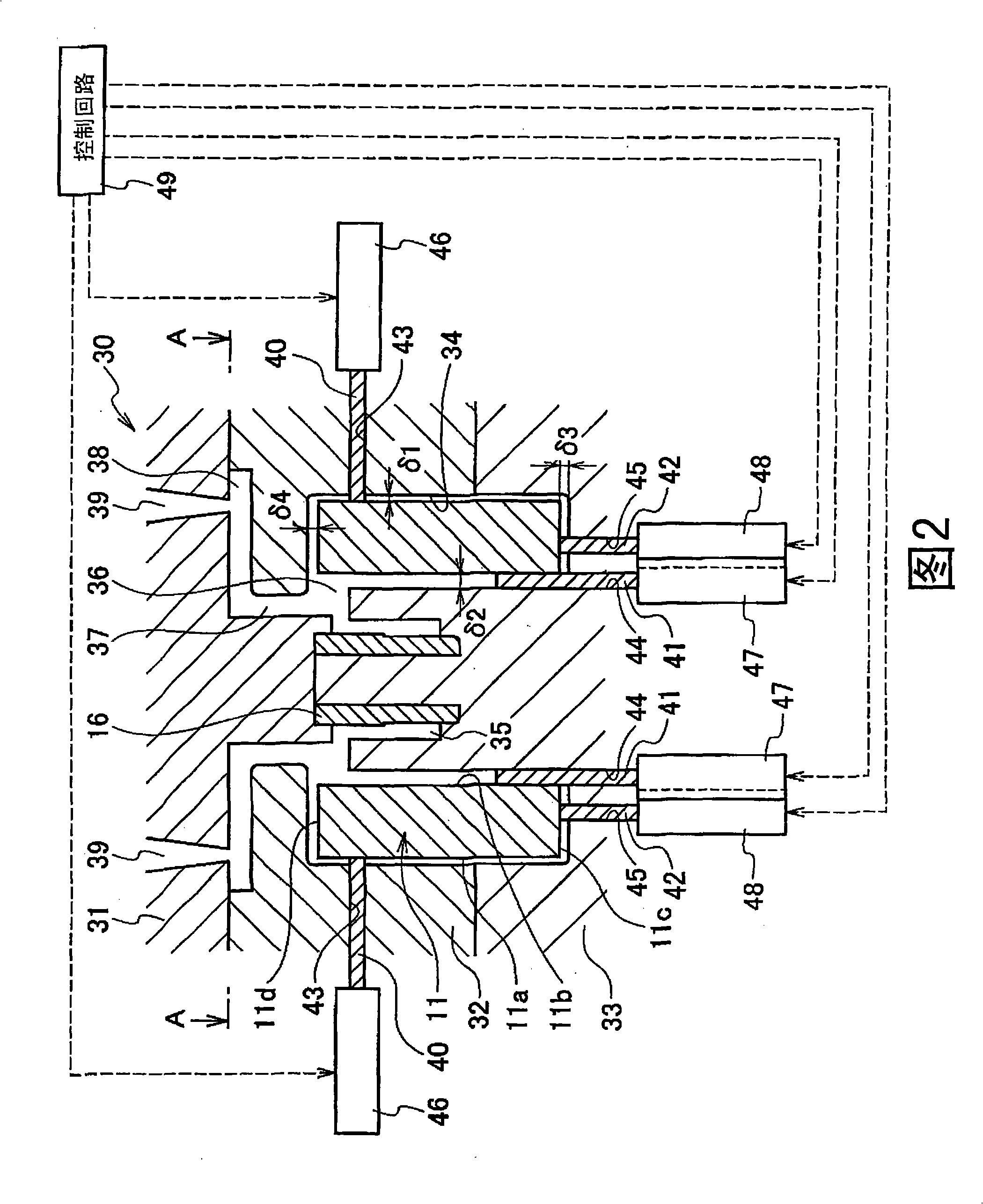
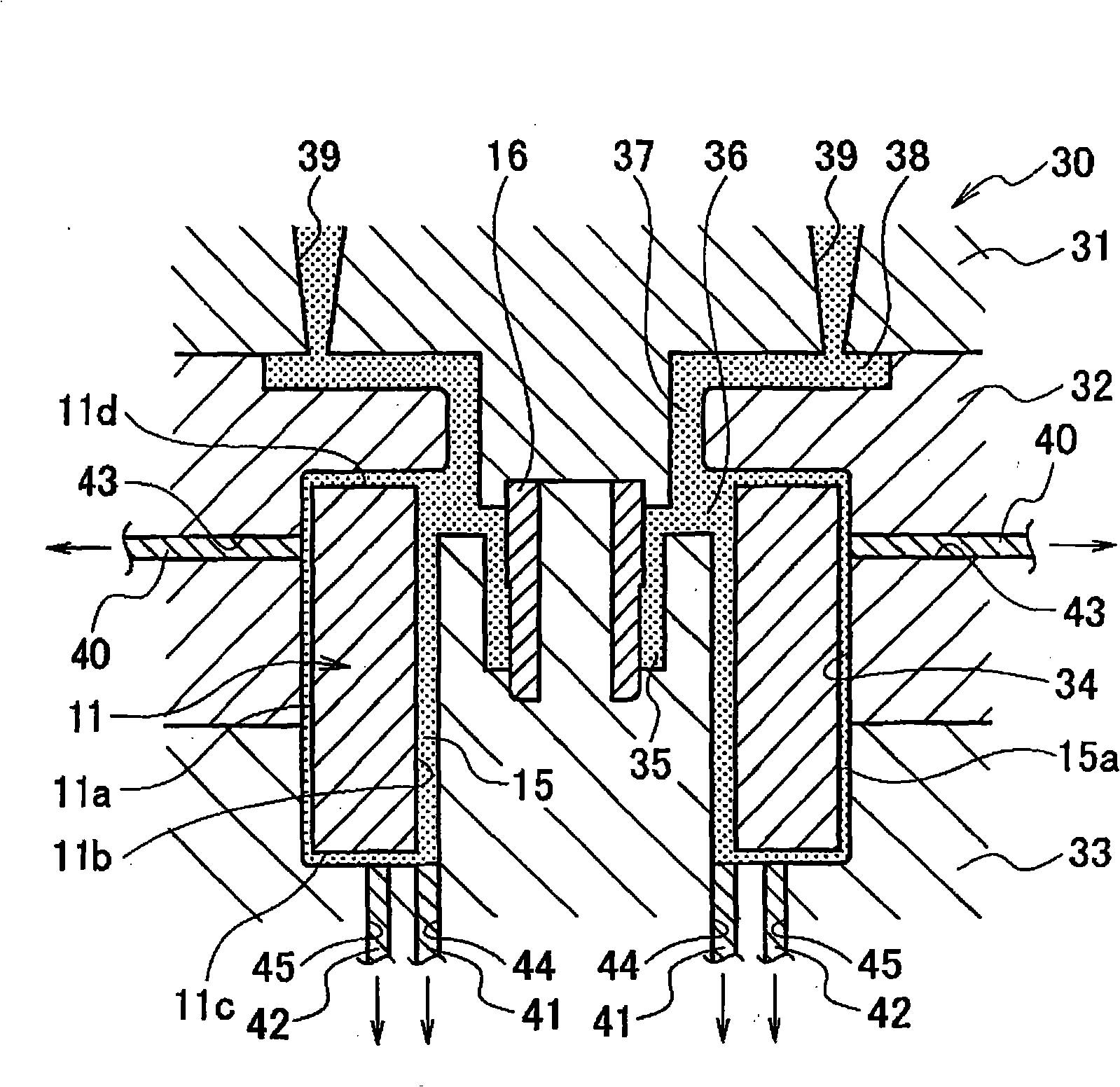
[0035] Hereinafter, an embodiment of the present invention will be described with reference to the drawings. Figure 1 ~ Figure 4 The motor-integrated pump of this embodiment is shown. among them, figure 1 It is a cross-sectional view of the motor-integrated pump, and Figure 2 is a cross-sectional view of the mold at the initial stage of manufacturing the rotor part of the motor-integrated pump. image 3 It is a cross-sectional view of the mold in the final stage of manufacturing the rotor part of the motor-integrated pump. Figure 4 It is a cross-sectional view taken along the line A-A in FIG. 2.

[0036] Such as figure 1 As shown, the motor-integrated pump (hereinafter referred to as the pump) 1 of the present embodiment is formed by integrally coupling a pump unit 2 arranged on the right side of the figure and a motor unit 3 arranged on the left side of the figure.

[0037] The pump unit 2 is housed in the pump housing 4 and includes: a scroll impeller 5; a suction port 6 for ...


PUM


Abstract

Provided are a manufacturing method of a rotor of a motor integrated pump capable of more reliably restraining the influence of operating fluid of the pump on the magnet and a motor integrated pump with the rotor is provided. The method includes: a magnet support process, supporting a magnet (11) inserted in a die (30) through a first, second and third pins (40,41,42); and a support component removing process, drawing out the first, second and third pins (40,41,42) from a first cavity (34) of the die (30) through a first, second and third implementation components (46,47,48) in the process of filling resin in the die (30). Therefore, even if in the region wherein, magnet is supported by the first, second and third pins (40,41,42), the shaping resin can be used to overcast.

Description

technical field [0001] The present invention relates to a method of manufacturing a rotor portion of a motor-integrated pump in which a pump unit and a motor unit are integrated, and a motor-integrated pump including the rotor portion. Background technique [0002] Conventionally, as a motor-integrated pump, for example, a centrifugal pump using an impeller disclosed in Patent Document 1 is known. In the motor unit of the motor-integrated pump disclosed in Patent Document 1, a stator portion having a coil is disposed around a peripheral surface (outer peripheral surface) of a rotor portion having an annular magnet, and the rotor portion is rotated by energizing the coil. The impeller is integrated with the rotor part to form a rotating device, and as the rotor part rotates, the impeller rotates to discharge the fluid. [0003] In the rotary device in which the rotor part and the impeller are integrated, first, the magnet is inserted into the mold, and thermoplastic resin is...

Claims


Application Information

Patent Timeline
IPC IPC(8): F04D13/06F04D29/22H02K15/03
CPCB29C45/14008B29C45/17B29C45/18B29D99/0025B29L2031/08F04D13/06F04D29/22F05D2210/11F05D2230/20F05D2240/20
Inventor 秋吉卓也住田安弘仓住博章原田高宏
Owner PANASONIC CORP
Why Eureka
Try Eureka