

Gravity type hot pipe trapezoid combined warming heat radiator
A gravity-type heat pipe and radiator technology, applied in indirect heat exchangers, lighting and heating equipment, etc., can solve the problems of low heat transfer coefficient, small heat dissipation area, and narrow use area, so as to improve heat transfer coefficient and ensure safe operation Reliable, the effect of increasing the heating area
- Summary
- Abstract
- Description
- Claims
- Application Information
AI Technical Summary
Problems solved by technology
Method used
Image

Examples
Embodiment 1
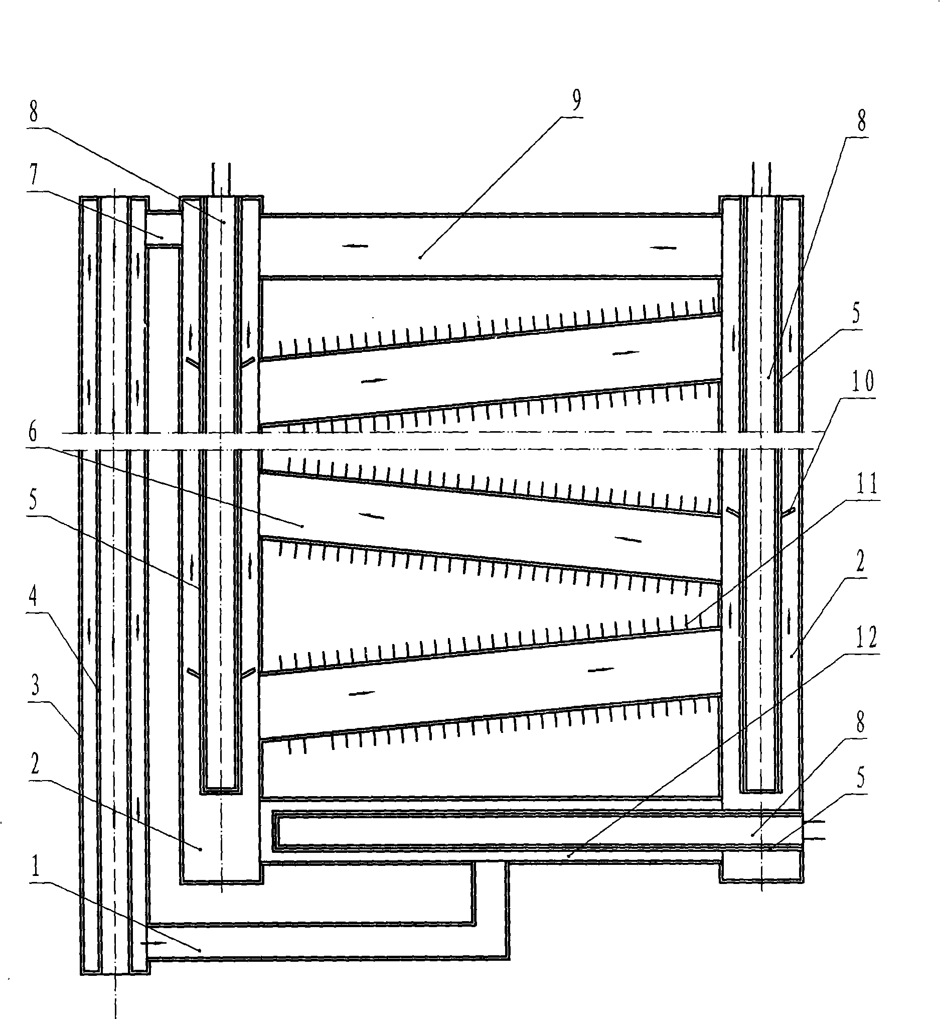
[0015] Such as figure 1 As shown, the present invention includes a liquid working fluid header 12, a heat exchanger 5, a finned cooling tube 6, a exhaust steam header 9 and a condensation return pipe; the condensation return pipe is composed of an inner pipe 4 and an outer pipe 3, And the two ends between the inner pipe 4 and the outer pipe 3 are closed to form a hollow closed sleeve, and the middle of the sleeve is for air flow to promote the condensation of the vapor working medium; the two ends of the liquid working medium header 12 are connected There is a superheater 2, and the heat exchanger 5 is located in the liquid working medium header 12 and the superheater 2, forming a U-shaped heat exchanger assembly; the heat exchanger 5 is a split type, and in the split heat exchanger 5 An electric heater 8 is installed to heat the liquid working medium in the U-shaped heat exchanger assembly; the finned heat pipe 6 has spiral fins 11 on the surface to facilitate heat dissipatio...
Embodiment 2
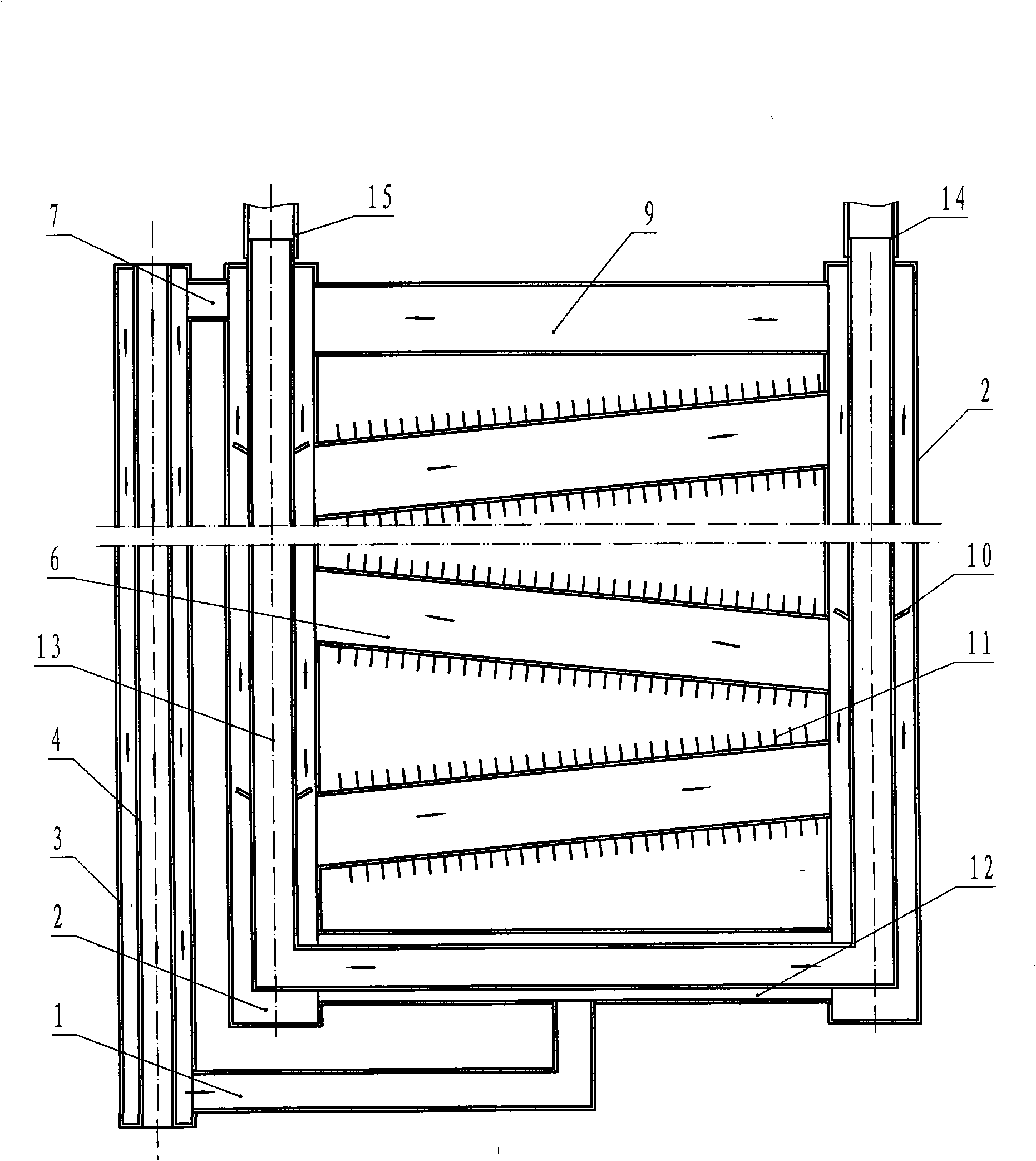
[0017] Such as figure 2 As shown, its structure is as embodiment 1, and the difference is that the heat exchanger 13 is an integral type, and there are heat source inlet joints 14 and heat source outlet joints 15 at both ends of the integral heat exchanger 13, and heat source inlet joints 14 and Steam or hot water is connected to the heat source outlet joint 15 as a heat source to heat the liquid working fluid in the U-shaped heat exchanger assembly.
PUM
 Abstract
Description
Claims
Application Information