
Oscillating circuit for detecting tiny plane coil inductance

A technology of planar coils and oscillating circuits, applied in the direction of measuring resistance/reactance/impedance, measuring electrical variables, measuring devices, etc., can solve problems such as large influence, inability to apply measurement, and the influence of sensor sensitive coil quality factors, so as to improve quality factor, the effect of signal output stabilization

Inactive Publication Date: 2009-04-15
TSINGHUA UNIV
View PDF0 Cites 4 Cited by
  • Summary
  • Abstract
  • Description
  • Claims
  • Application Information

AI Technical Summary

Problems solved by technology

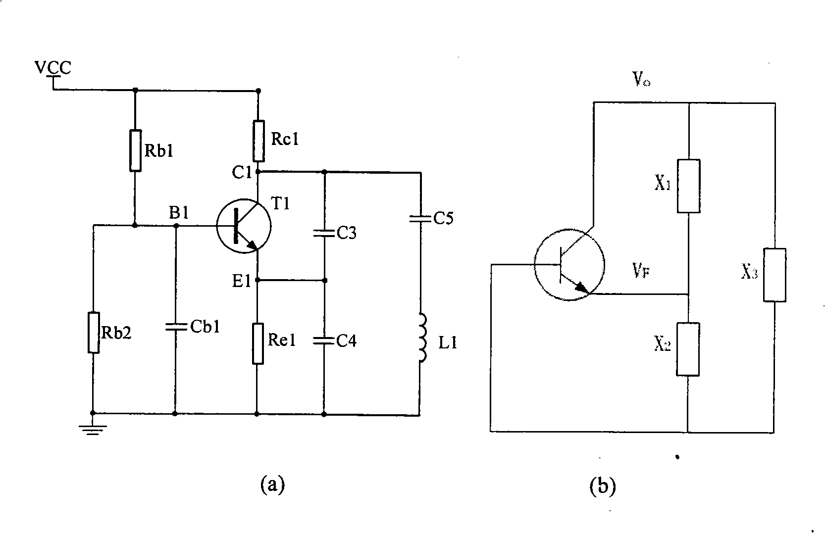
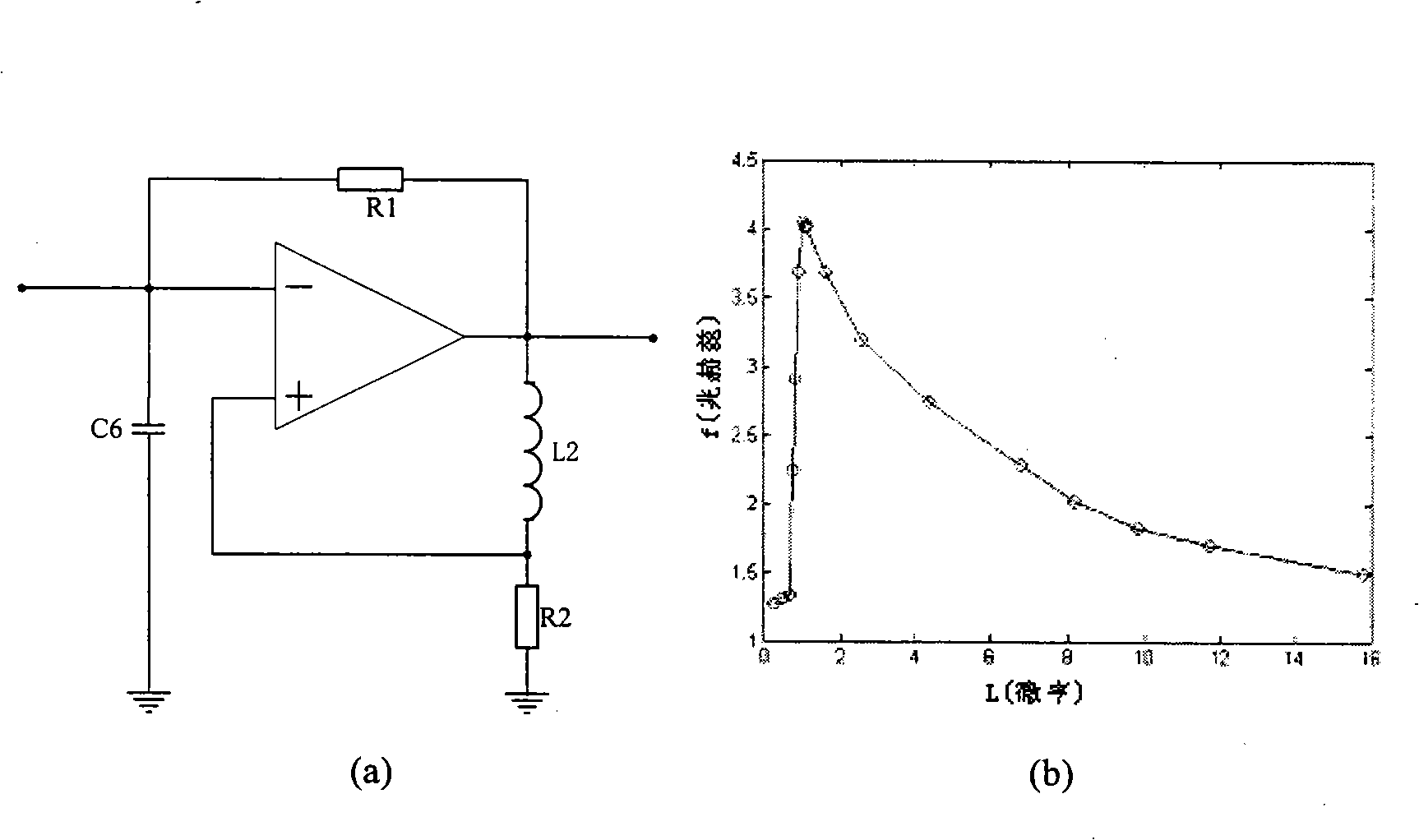
It can be seen that the start-up of the differential relaxation oscillation circuit has nothing to do with the resistance parameters of the sensitive coil and the transmission cable, but it is still affected by the quality factor of the sensitive coil of the sensor
Moreover, the main disadvantage of the differential relaxation oscillation circuit is the poor stability of the output signal, which is also greatly affected by the device parameters.
Its short-term stability generally can only reach 10 -3 Although it has been improved (mainly by adding capacitance), its short-term stability can reach 10 -4 , but still cannot be applied to the measurement of mechanical quantities such as displacement

Method used


Image

  • Oscillating circuit for detecting tiny plane coil inductance
  • Oscillating circuit for detecting tiny plane coil inductance
  • Oscillating circuit for detecting tiny plane coil inductance

Examples


Embodiment Construction

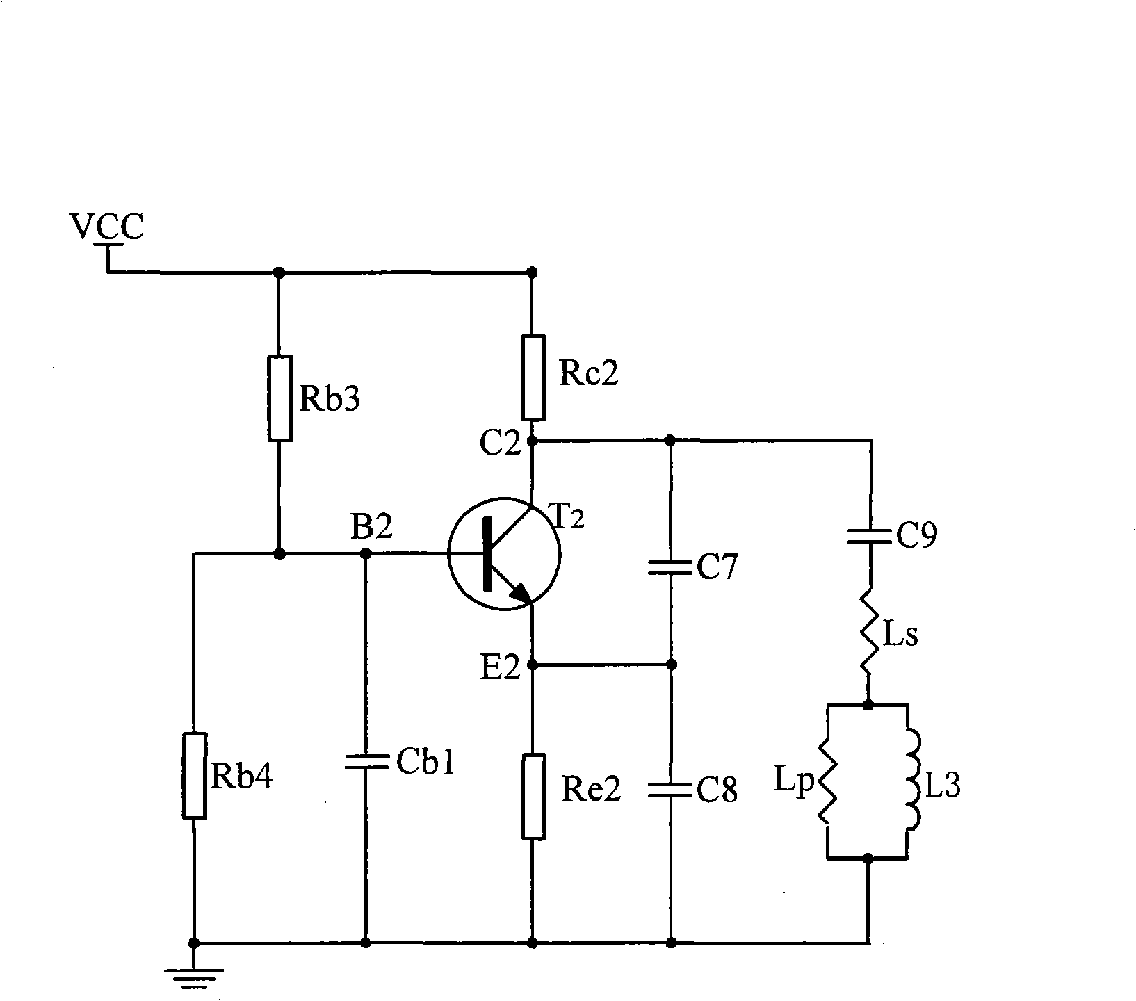
[0021] The oscillating circuit used to detect the inductance of the tiny planar coil proposed by the present invention, the circuit diagram is as follows image 3 As shown, it includes: a triode T2, four resistors Rb3, Rb4, Rc2 and Re2, four capacitors C6, C7, C8 and Cb2, two inductors Ls, Lp and the measured planar coil inductance L3; the resistor Rc2 One end of the resistor Rc2 is connected to the power supply, the other end of the resistor Rc2 is connected to the collector C2 of the transistor T2, the collector C2 of the transistor T2 is connected to one end of the capacitor C7, and the other end of the capacitor C7 is connected to the emitter E2 of the transistor T2 The emitter E2 of the transistor T2 is connected to one end of the resistor Re2 and one end of the capacitor C8 at the same time, the other end of the resistor Re2 and the other end of the capacitor C8 are respectively grounded, one end of the resistor Rb3 is connected to the power supply, and the other end of t...


PUM


Abstract

The invention relates to an oscillatory circuit used for detecting the coil inductance of a miniature plane, belonging to the technical field of electronics detection. A resistance Rc2 is connected with a power supply and a collector of a triode, a capacitor C7 is connected with an emitter of the triode, the emitter is connected with a resistance Re2 and the capacitor, the Re2 and a capacitor C8 are respectively ground, a resistance Rb3 is connected with the power supply and the base of the triode, the base is connected both with a resistance Rb4 and with a Cb2, the two of which are respectively ground, the collector and one end of a capacitor C9 are connected, the capacitor C9 is connected with an inductor Ls, and the inductor Ls is connected with an inductor Lp and the coil L3 of the detected plane, the three of which are respectively ground.In the oscillatory circuit, a sensor coil is connected with the inductor Lp in parallel and then connected to a capacitance connecting three point type oscillator, thus effectively improving the quality factor of the circuit system and leading to stable signal output of current vortex coil.

Description

technical field [0001] The invention relates to an oscillating circuit for detecting the inductance of a tiny planar coil, which belongs to the technical field of electronic detection. Background technique [0002] The concept of "compliant sensor" can be traced back to the late 1980s. Many special structures in aerospace vehicles have brought great difficulties to the installation of traditional rigid sensors. People hope that the sensor has good flexibility, is not limited by the shape of the object to be measured, and can be attached to various regular or irregular surfaces to achieve normal sensing functions. After entering the 1990s, scientists in the United States, France, Japan, Switzerland, Portugal and other countries began to conduct research on compliant sensors, and many new sensor materials and structures were applied to this research field. [0003] Eddy current testing technology is a non-destructive, non-contact measurement testing technology. The eddy curr...

Claims


Application Information

Patent Timeline
IPC IPC(8): G01R27/26
Inventor 王鹏丁天怀胡颖
Owner TSINGHUA UNIV
Learn More