Surface heat light source, preparation method thereof and method for heating object using the same

一种热光源、物体的技术,应用在光源、电光源、欧姆电阻加热等方向,能够解决面热光源热辐射及光辐射不均匀、热辐射传递距离近、热辐射效率低等问题,达到良好导电性能以及热稳定性、热辐射传递距离远、热辐射效率高的效果

Active Publication Date: 2009-04-15
TSINGHUA UNIV +1
View PDF0 Cites 26 Cited by
  • Summary
  • Abstract
  • Description
  • Claims
  • Application Information

AI Technical Summary

Problems solved by technology

However, the existing surface heat light source has the following disadvantages: first, the tungsten filament is a gray body structure, the temperature rises slowly, the heat radiation efficiency is low, and the heat radiation transmission distance is short; The radiation is not uniform; third, the tungsten wire has high strength, difficult processing and needs to work in an inert gas environment

Method used


Image

  • Surface heat light source, preparation method thereof and method for heating object using the same
  • Surface heat light source, preparation method thereof and method for heating object using the same
  • Surface heat light source, preparation method thereof and method for heating object using the same

Examples


Embodiment Construction

[0019] The surface heat light source of the technical solution, its preparation method and its application method for heating objects will be described in detail below in conjunction with the accompanying drawings.

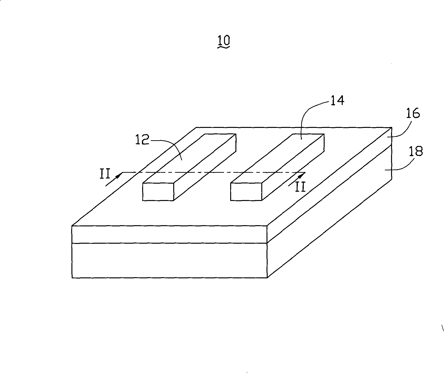
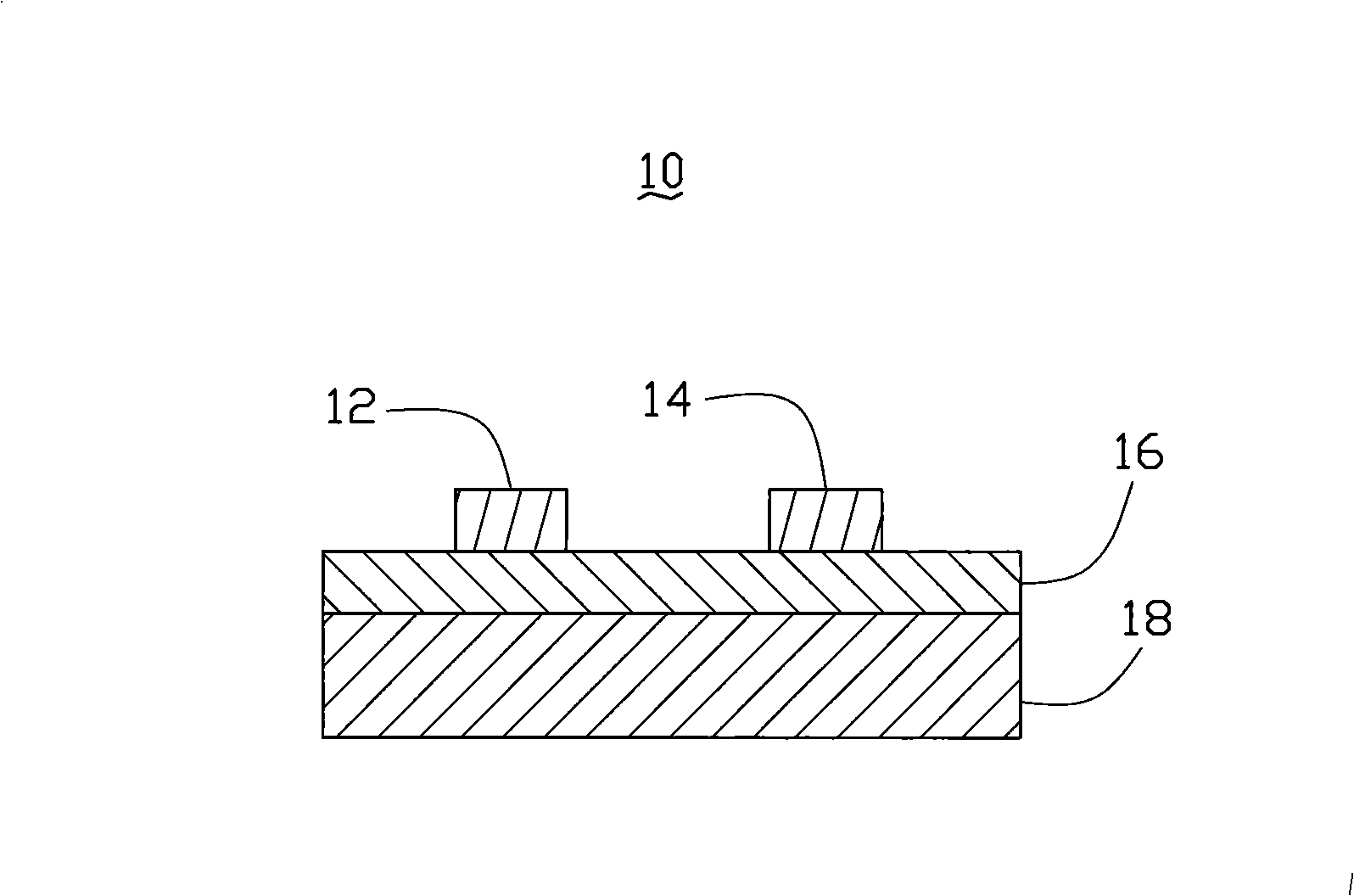
[0020] see figure 1 and figure 2 The embodiment of the technical solution provides a surface heat light source 10 , the surface heat light source 10 includes a first electrode 12 , a second electrode 14 , a carbon nanotube film 16 and a support 18 . The carbon nanotube film 16 is disposed on the support 18 . The first electrode 12 and the second electrode 14 are disposed on the carbon nanotube film 16 , with a certain distance between the first electrode 12 and the second electrode 14 , and are in electrical contact with the surface of the carbon nanotube film 16 .

[0021] Further, the carbon nanotube film 16 includes intertwined carbon nanotubes, and the carbon nanotubes attract and intertwine with each other through van der Waals force to form a network stru...


PUM

PropertyMeasurementUnit
lengthaaaaaaaaaa
pore sizeaaaaaaaaaa
lengthaaaaaaaaaa

Abstract

The invention relates to a surface heating light source, comprising a first electrode, a second electrode and a carbon nano-tube film; the first electrode and the second electrode are arranged on the carbon nano-tube film; the first electrode and the second electrode have a certain distance and electrically contact with the surface of the carbon nano-tube film; the carbon nano-tube film internally comprises carbon nano-tubes which enwind each other. The invention also relates to a preparation method used for preparing surface heating light source, comprising the steps as follows: carbon nano-tube raw material is provided; the carbon nano-tube raw material is added in solvent and carries out flocking disposal, thus gaining a carbon nano-tube floceulent structure; the carbon nano-tube floceuelent structure is separated from the solvent and shapes the carbon nano-tube floceulent structure so as to gain a carbon nano-tube film; the first electrode and the second electrode are provided; the first electrode and the second electrode are intermittently arranged on the surface of the carbon nano-tube film and form electric contact on the surface of the carbon nano-tube, thus gaining a surface heat light source. The invention also relates to a method used for heating the article by adopting the surface heat light source and comprises the steps as follows: an article to be heated is provided; the article is provided with a surface; the carbon nano-tube film in the surface heat light source is arranged closely to the surface of the article to be heated; voltage is applied to the electrodes in the surface heat light source so as to heat the article.

Description

technical field [0001] The invention relates to a surface heat light source, its preparation method and its application method for heating objects, in particular to a surface heat light source based on carbon nanotubes, its preparation method and its application method for heating objects. Background technique [0002] Since Japanese scientist Iijima first discovered carbon nanotubes (Carbon Nanotube, CNT) in 1991 (see Helical microtubules of graphitic carbon, Nature, Sumio Iijima, vol354, p56 (1991)), nanomaterials represented by carbon nanotubes have been Its unique structure and properties have attracted great attention. In recent years, with the continuous deepening of research on carbon nanotubes and nanomaterials, their broad application prospects continue to emerge. For example, due to the unique electromagnetic, optical, mechanical, and chemical properties of carbon nanotubes, a large number of applications in the fields of field emission electron sources, sensors, ...

Claims


Application Information

Patent Timeline
Patent Type & Authority Applications(China)
IPC IPC(8): H05B33/12H05B33/14H05B33/26
CPCH01J29/30H01J29/20H05B2214/04Y10S977/742B82Y99/00H01J9/18H05B3/009H05B3/145H05B3/34
Inventor 刘长洪范守善
Owner TSINGHUA UNIV
Why Eureka
Try Eureka