Numerical control machining method based on rigid construction parts and clamping fixture for numerical control machining

A technology of rigid structure and processing method, applied in the direction of manufacturing tools, metal processing equipment, metal processing machinery parts, etc., can solve problems such as the inability to meet the development cycle of parts and the poor deformation effect of parts, so as to shorten the development cycle and improve the processing efficiency. and quality, good economic effect

Active Publication Date: 2010-06-09
XIAN AIRCRAFT IND GROUP
View PDF0 Cites 0 Cited by
  • Summary
  • Abstract
  • Description
  • Claims
  • Application Information

AI Technical Summary

Problems solved by technology

The advantage of this method is that the clamping and positioning are fast, and the deformation of the parts has been improved compared with the previous method, but the effect of controlling the deformation of the parts is not good.
Furthermore, the development of tooling has a certain cycle, and in the trial production process, there is a certain coordination cycle between parts and tooling, which cannot meet the development cycle of parts.

Method used


Image

  • Numerical control machining method based on rigid construction parts and clamping fixture for numerical control machining
  • Numerical control machining method based on rigid construction parts and clamping fixture for numerical control machining
  • Numerical control machining method based on rigid construction parts and clamping fixture for numerical control machining

Examples


Embodiment Construction

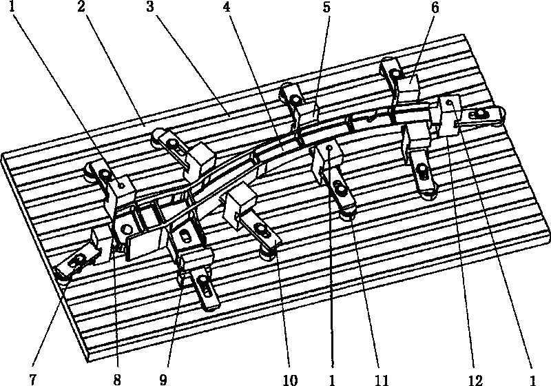
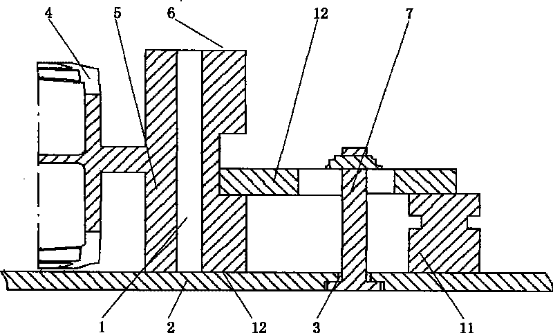
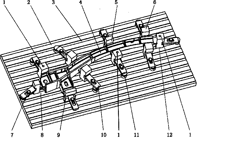
[0016] refer to figure 1 , figure 2 A positioning and clamping view and a partial cross-sectional view of an embodiment of the present invention are shown. Now describe this invention in conjunction with accompanying drawing.

[0017] The part body 4 to be processed in the figure is the main load-bearing frame part of the aircraft fuselage. This part has the characteristics of high rigidity and complex structure. The process plan of CNC machining of such parts is arranged according to the rough machining, semi-finishing, and finishing procedures of the blank first, and the auxiliary process and inspection process are properly arranged. Especially for frame parts with large deformation, the flatness is not guaranteed. The aging process should also be properly arranged.

[0018] When implementing the rough machining of the part blank, a plurality of process bosses 5 are reserved around the part body 4 through rough machining, and there is an uninterrupted connection between ...


PUM


Abstract

The invention aims to provide a method for processing rigid structure parts through digital control and a clamp structure for processing the rigid structure parts through the digital control. The method mainly comprises the following steps: performing rough machining on part blanks, processing a plurality of process lug bosses with the equal height on the periphery of the contour surface of the parts in the process of the rough machining, and processing a rigid connecting bridge between the process lug bosses and the contour surface of the parts to make the process lug bosses connected with the contour surface of the parts continuously. The process lug bosses are evenly distributed on the periphery of the contour of the parts according to the differences of the part structures, and the weaker parts of the part structures are provided with more process lug bosses properly. One of the advantages of the method is to use the process lug bosses combined with the parts to replace special fixtures so as to save the manufacturing cost.

Description

technical field [0001] The invention relates to the technical field of aircraft manufacturing, in particular to the numerical control machining of aircraft fuselage frame parts, and is also applicable to a machining method and a numerical control machining fixture for numerical control machining of similar rigid structural parts. Background technique [0002] As we all know, the clamping and positioning of the parts to be processed in CNC machining is one of the key links that affect the processing quality and processing efficiency of the parts. Aircraft frame parts are typical rigid structural parts. The traditional clamping methods are roughly divided into two types. One is to directly mill the parts on the wool until the parts are processed and then separate from the wool. The advantage of this method is that it saves time. But the disadvantage is that after the parts are separated from the wool, the parts are greatly deformed and cannot meet the design requirements. Th...

Claims


Application Information

Patent Timeline
Patent Type & Authority Patents(China)
IPC IPC(8): B23C3/00B23Q3/06
Inventor 周文东周鹏龚斌王俊斌郑小伟
Owner XIAN AIRCRAFT IND GROUP
Why Eureka
Try Eureka