
Method for welding rocking arc narrow clearance melting electrode with gas protection and welding torch

A technology of molten electrode gas and shielded welding, which is applied in the direction of arc welding equipment, welding equipment, electrode support devices, etc., can solve the problems of increased welding cost, large wear of the contact tip, and low service life, and achieves reduced welding cost and high welding quality , long life effect

Inactive Publication Date: 2011-06-01
JIANGSU UNIV OF SCI & TECH
View PDF1 Cites 0 Cited by
  • Summary
  • Abstract
  • Description
  • Claims
  • Application Information

AI Technical Summary

Problems solved by technology

The disadvantages of this method and device are: (1) Like other types of rotary arc welding methods, it cannot be used for welding in spatial positions; (2) The high-speed rotation of the contact tip causes high-speed relative motion between the welding wire and the contact tip, resulting in The contact tip wears a lot and has a low service life, and the eccentric contact tip is a non-standard part and needs to be specially made, thus significantly increasing the welding cost

Method used


Image

  • Method for welding rocking arc narrow clearance melting electrode with gas protection and welding torch
  • Method for welding rocking arc narrow clearance melting electrode with gas protection and welding torch
  • Method for welding rocking arc narrow clearance melting electrode with gas protection and welding torch

Examples


Embodiment Construction

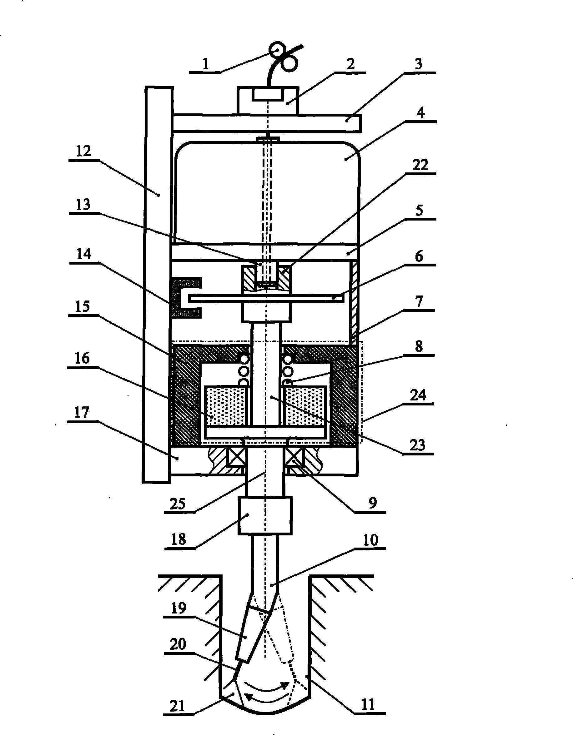
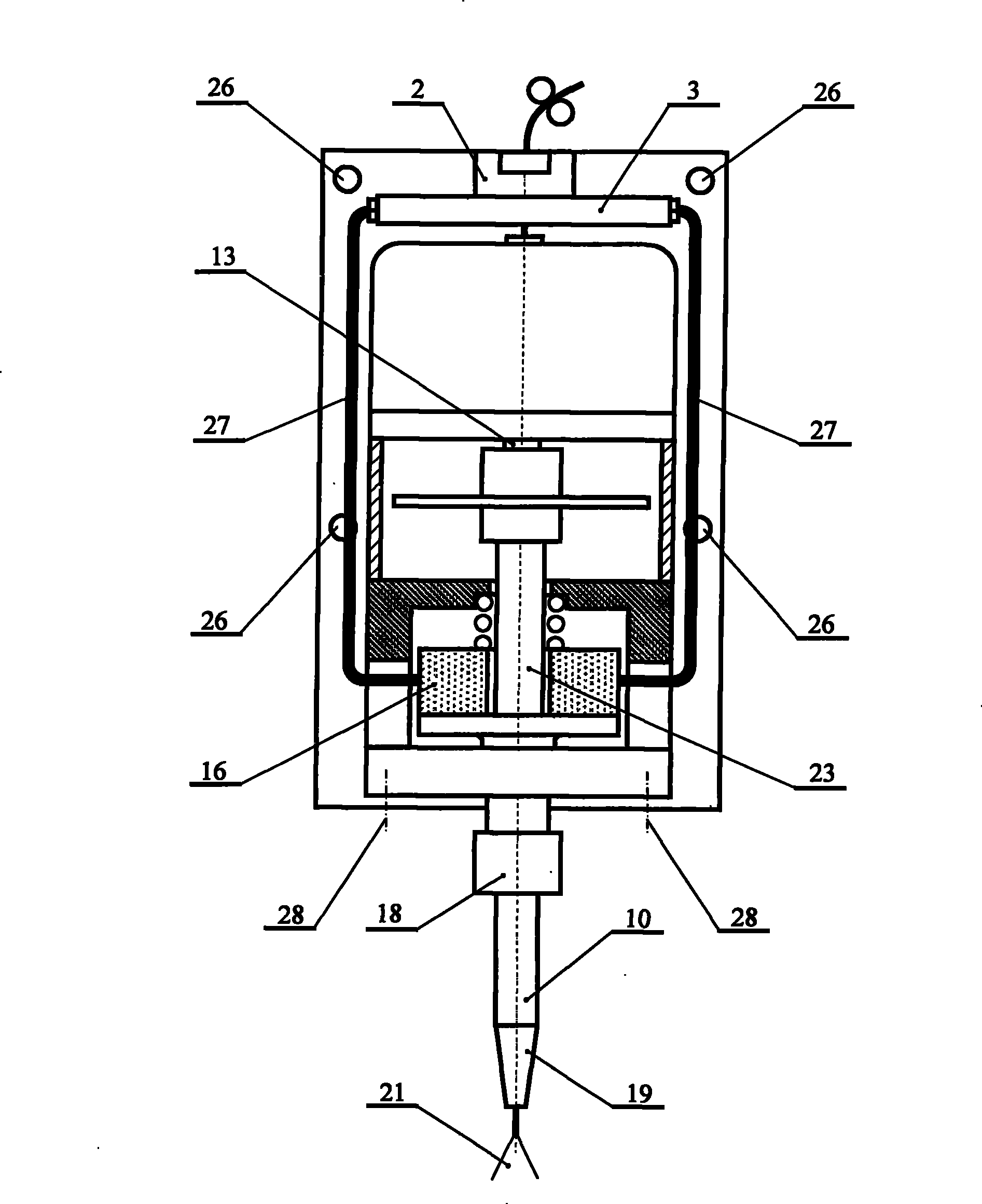
[0022] Such as figure 1 , 2 As shown, the welding wire 20 sent by the wire feed roller 1 penetrates through the central hole of the coupling head 2, passes through the central hole of the coupling head support 3, the hollow shaft of the motor 13, the coupling 22, the straight conductive rod 23, and the connecting piece 18. After the central hole of the slightly bent conductive rod 10 , pass through the central hole of the conductive tip 19 to generate a welding arc 21 at the groove 11 of the workpiece. It adopts the general-purpose gas shielded welding machine cable connection head 2, so that the welding torch can be conveniently connected with the feeder cable of the general-purpose welding machine. The hollow shaft motor 4 is installed on the motor support 5 , and the lower end of the motor hollow shaft 13 passes through the motor support 5 and is connected with the coupling 22 . The connecting cable 27 is fixedly connected to the brush mechanism 24 and the coupling head 2...


PUM


Abstract

The invention discloses a rocking arc narrow gap consumable electrode gas shielded welding method and a welding torch. The method comprises the following steps: a connecting cable is fixed on an electric brush mechanism and a coupling head; a hollow shaft motor is connected with a straight conducting rod through a shaft joint; a welding wire passes through a center hole of a cable coupling head, and penetrates out a center hole of a current contact nozzle; the lower end of the straight conducting rod is fixed with a connecting piece; and one end of a minor bend conducting rod is connected with the straight conducting rod through the connecting piece, while the other end of the minor bend conducting rod is connected with the current contact nozzle. The hollow shaft motor directly drives the straight conducting rod and the minor bend conducting rod capable of extending into a divided edge of a workpiece to make reciprocating rotation around the central axial line of the welding torch, thereby driving electric arc of the end of the welding wire send from the center hole of the current contact nozzle to make arc rocking in the divided edge of the workpiece so as to realize rocking arcnarrow gap welding. The welding torch has the advantages of simple and compact structure, low implementation cost, high reliability of operation, strong practicality, and can adapt requirement of welding process for mean position and spatial position with different welding seams. The welding wire has strong rocking regulation, good directivity of the electric arc, and high welding quality.

Description

technical field [0001] The invention relates to an oscillating arc narrow-gap melting electrode gas shielded welding method driven by a hollow shaft motor and a welding torch, belonging to the field of welding technology. Background technique [0002] Narrow-gap MIGA welding is a mechanized or automatic arc welding method in which gas is used as a protective medium and the welding wire is automatically fed into the welding zone. It is suitable for occasions where the base metal plate thickness is generally greater than 30mm and the I-shaped groove gap is less than 20mm. . This process uses gas shielding, no slag removal after welding, can be welded in space, moderate welding heat input, good manufacturability, superior comprehensive technology and economic performance, is an advanced welding technology with high efficiency, high quality and low cost. received great attention from the people. How to ensure uniform and stable penetration on both sides of the groove is one of...

Claims


Application Information

Patent Timeline
Patent Type & Authority Patents(China)
IPC IPC(8): B23K9/173B23K9/28
Inventor 王加友杨峰韩伟黎文航
Owner JIANGSU UNIV OF SCI & TECH
Learn More