LED radiator

A technology of light-emitting diodes and heat sinks, which is applied in the field of heat sinks, can solve problems such as weight gain and volume increase of lighting devices, and achieve the effects of enhancing natural convection, reducing weight, and increasing heat dissipation area

Inactive Publication Date: 2009-04-22
CHAMP TECH OPTICAL FOSHAN +1
View PDF1 Cites 1 Cited by
  • Summary
  • Abstract
  • Description
  • Claims
  • Application Information

AI Technical Summary

Problems solved by technology

In order to improve its heat dissipation efficiency, it is generally necessary to increase the number of heat dissipation fins or increase the size of heat dissipation fins, but this will increase the volume and weight of the LED heat sink and the entire lighting device.

Method used


Image

  • LED radiator
  • LED radiator
  • LED radiator

Examples


Embodiment Construction

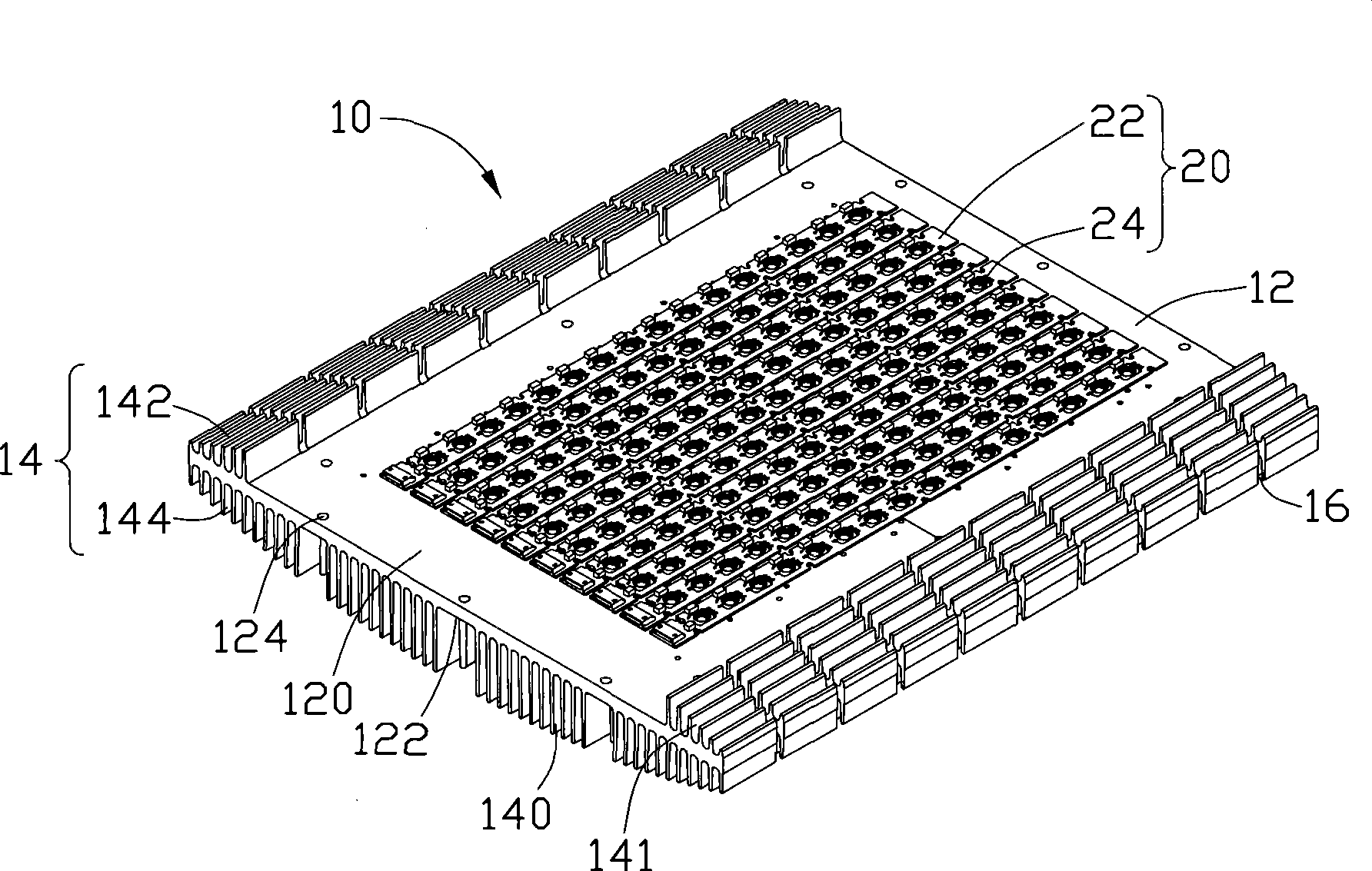
[0011] see Figure 1 to Figure 3 , is the light-emitting diode heat sink 10 in a preferred embodiment of the present invention, which is used to dissipate heat from the light-emitting diode module 20 . The LED module 20 is generally used as a light source of a lamp (not shown).

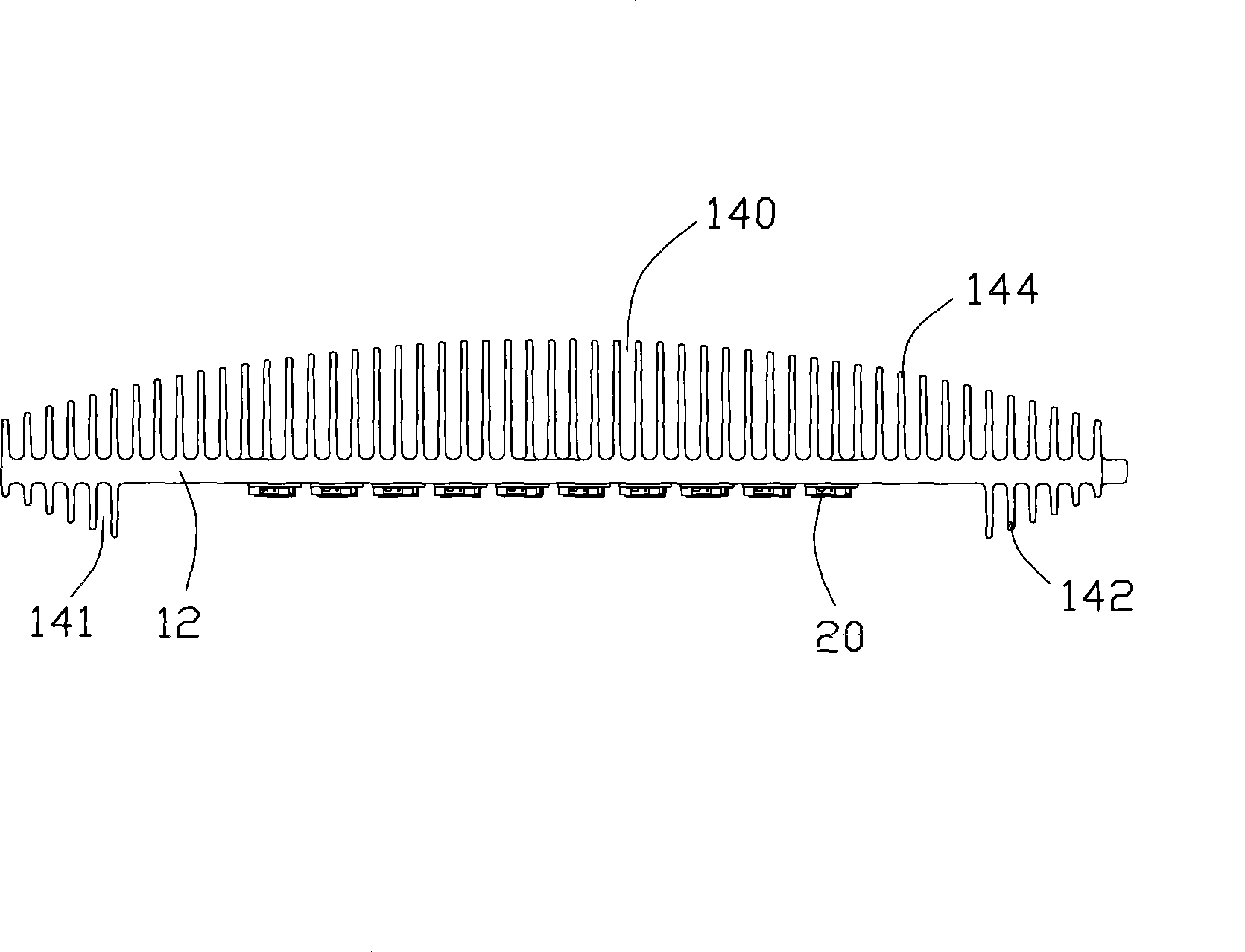
[0012] The light-emitting diode module 20 is closely attached to the bottom surface of the light-emitting diode heat sink 10, and includes a plurality of circuit boards 22 and a plurality of light-emitting diodes 24 that are parallel to each other. The circuit board 22 is electrically connected.

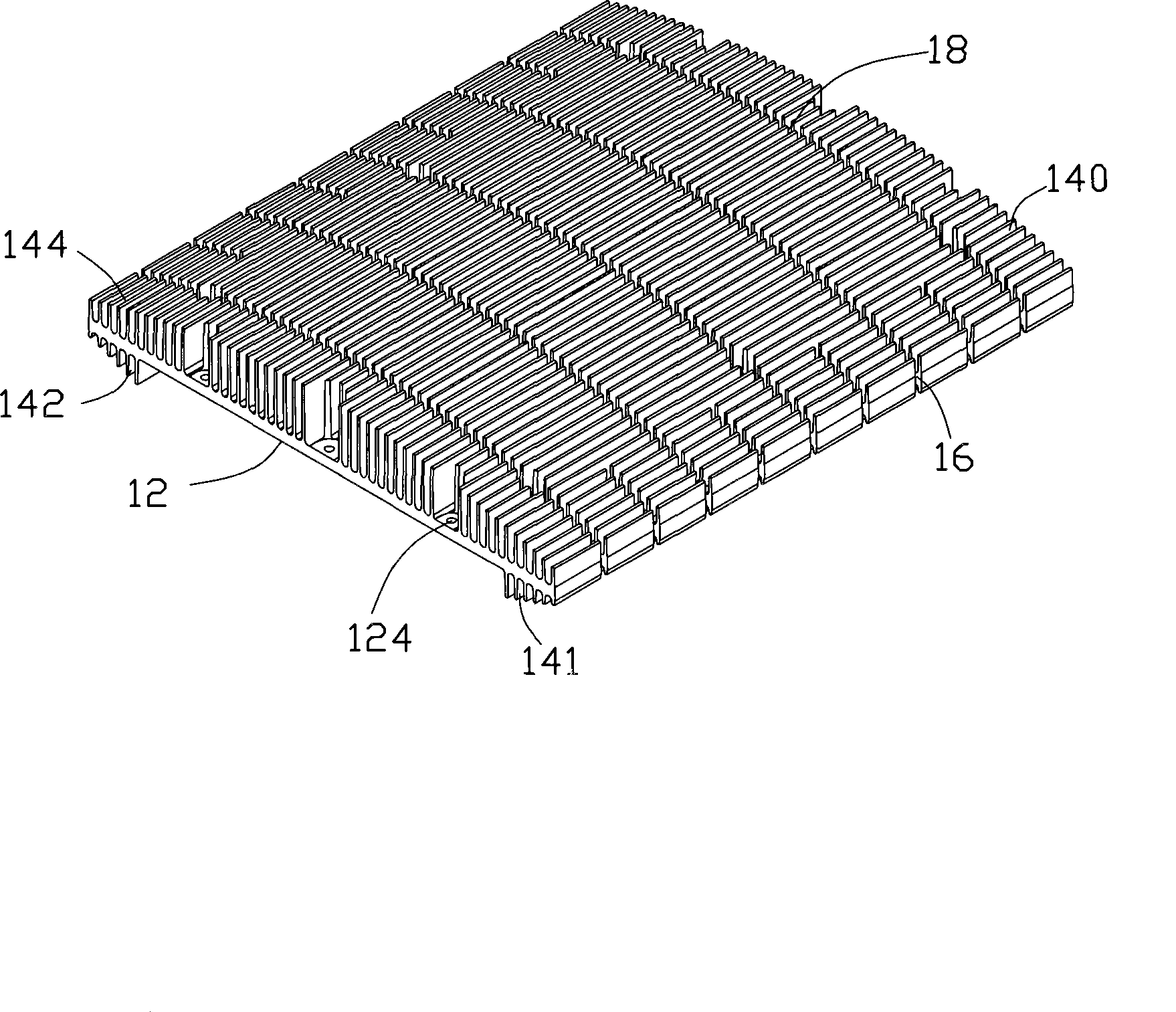
[0013] The LED heat sink 10 is made of a metal or alloy with high thermal conductivity, such as copper, aluminum or copper-aluminum alloy, and includes a substantially rectangular plate-shaped substrate 12 and a plurality of vertically extending from the surface of the substrate 12 . cooling fins 14 . The substrate 12 has a bottom surface 120 and a top surface 122 opposite to the bottom surface 120 . The...


PUM


Abstract

A light-emitting diode radiator comprises a substrate for affixing a light-emitting diode module and a plurality of cooling fins which are extended from the substrate, the cooling fins comprise first cooling fins and second cooling fins which are respectively extended from two reverse surfaces of the substrate, airflow channels are respectively formed in the various fins, and a plurality of notches which are inward extended and at least cut off part of the first cooling fins and the second cooling fins are arranged at the two sides of the substrate. Compared with the prior art, the cooling fins are formed on the two opposite surfaces of the substrate of the light-emitting diode radiator, thereby increasing the cooling area of the light-emitting diode radiator; meanwhile, a plurality of notches which are inward extended and cut off part of the cooling fins are arranged at the two sides of the substrate, the weight of the light-emitting diode radiator is reduced, and the natural convection of air in the cooling fins is enhanced, thereby upgrading the cooling efficiency of the light-emitting diode radiator under the premise of not increasing the size of the light-emitting diode radiator and the density of the cooling fins.

Description

technical field [0001] The invention relates to a radiator, in particular to a light emitting diode radiator. Background technique [0002] Light Emitting Diode (LED) is a semiconductor light-emitting device, which uses a semiconductor chip as a light-emitting device. In the semiconductor, the excess energy is released by the recombination of carriers, causing photon emission, which directly emits red and blue. Light-emitting diode lighting products are lighting fixtures that use light-emitting diodes as light sources, and are widely used in communications, lighting, transportation, outdoor signage and other fields. However, high-brightness, high-power light-emitting diodes will significantly reduce the luminous efficiency due to the increase in temperature, and even cause damage to the components, and this problem is more prominent in the field of lighting. Therefore, how to keep the working temperature of the light-emitting diode within a certain range to avoid the above ...

Claims


Application Information

Patent Timeline
Patent Type & Authority Applications(China)
IPC IPC(8): H01L23/367F21V29/00H05K7/20F21V29/508F21V29/71
Inventor 张文祥余光赖振田
Owner CHAMP TECH OPTICAL FOSHAN
Why Eureka
Try Eureka