Quick energy-saving automatic aligning cutting-off device

A cutting machine and automatic technology, which is applied in the field of automatic straightening and cutting machines, can solve the problems of production cost and electric energy waste, user troubles, oil pump start-up in advance, etc., to reduce processing and production costs, low manufacturing and production costs, and reduce multi-section variable speed Effect

Inactive Publication Date: 2009-04-29
龙乐武
View PDF0 Cites 8 Cited by
  • Summary
  • Abstract
  • Description
  • Claims
  • Application Information

AI Technical Summary

Problems solved by technology

Adopting the control shearing structure of mechanical transmission must use multiple conjoined spur gears of different sizes and the method of multi-stage speed change to complete, especially the mobile saw gear 14 that controls the clutch shearing and the conjoined rotary wheel on the clutch shaft. The fast engagement of the fixed saw gear 13, and the separation and positioning hook device, due to the large diameter, heavy weight and fast shearing speed of the large gear of the shearing knife, the impact inertia force generated when cutting steel bars is particularly large, in actual use The control of the positioning hook often fails, resulting in continuous rotation of the large shearing gear, and the waste of non-stop cutting short steel bars. Normal use
In order to keep up with the market, it is necessary to solve the problem of fast shearing gear, large recoil inertial force, unstable mechanical performance, control positioning hook, contact wear and tear, and control failure. Many domestic manufacturers have successively Developed and produced the automatic straightening and cutting machine with oil pump hydraulic propulsion and shearing method. Due to the different transmission structure of the oil pump hydraulic shearing straightening machine, it is necessary to use 3 motors to work at the same time
①Straightening system: A 5.5KW motor directly drives the straightening cylinder to straighten the steel bars; ②A 3KW motor drives a special matching reduction box device to pull the feeding roller, and at the same time drive the wire and steel bars in the straightening cylinder to pull Send out; ③Use a 4KW motor to drive the shearing hydraulic oil pump. When the steel bar needs to be cut to a fixed length, the fixed-length stroke switch on the runway frame is connected to the electric control switch of the oil pump valve. Under the pressure of the driving rotation, it enters the oil cylinder through the high-pressure oil pipe, and pushes out the piston knife rod in the oil cylinder. The blade installed on the piston knife rod and the fixed blade on the movable knife holder are pushed sideways to cut off the steel bar in the raceway groove. The cutting speed is about 40 meters per minute. It takes about 15 degrees of electricity to straighten and cut 1 ton of wire rod steel. However, the working time of actual cutting, feeding and retracting, and returning takes about 1.5 seconds to complete each time, and the output length of the straight steel bar is adjusted to about 66 centimeters per second. In this way, a The cut-off steel bars with a length of about one meter cannot be completed, which adds a trouble of manual cutting to the user
2. The hydraulic oil in the fuel tank of the oil pump is affected by different regions and seasons at the same time. Especially in winter, the oil pump must be started in advance. After the temperature in the oil pump rises, the whole machine can be started and used normally, which brings some troubles and troubles to the user. inconvenient
3. Because the machine adopts hydraulic pressure, the structure of shearing traction and feeding is different, the whole machine needs 3 motors to work at the same time, resulting in high production cost and waste of electric energy

Method used


Image

  • Quick energy-saving automatic aligning cutting-off device
  • Quick energy-saving automatic aligning cutting-off device
  • Quick energy-saving automatic aligning cutting-off device

Examples


Embodiment 1

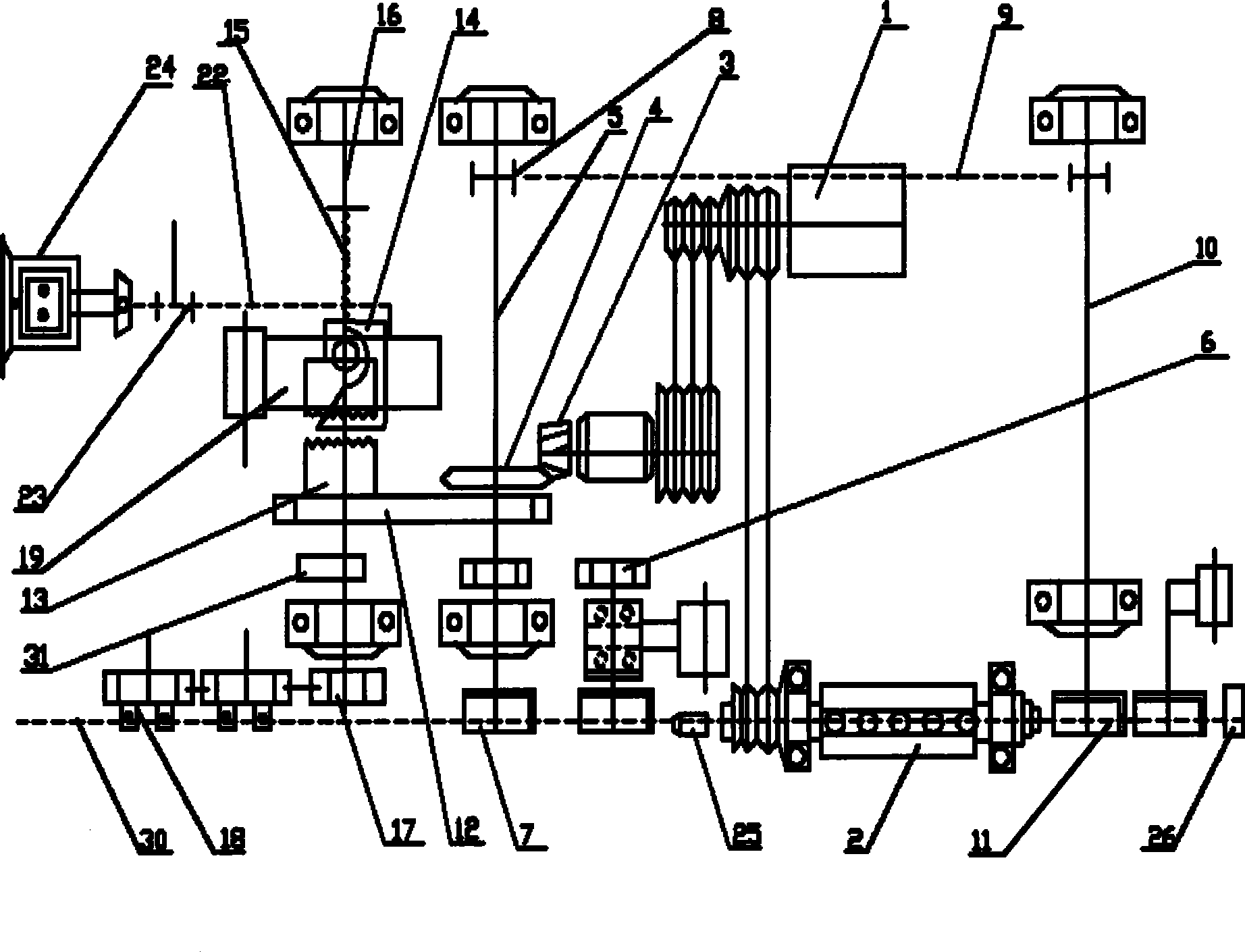
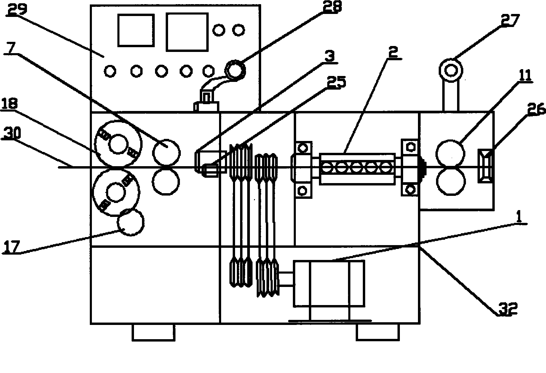
[0033] Embodiment 1, fast and energy-saving automatic straightening and cutting machine, wherein: the motor 1 drives the straightening cylinder 2 through one belt; the motor 1 drives the angled pulley, the rear axle angle gear 3, and the disc gear 4 in sequence through another belt at the same time , Front feeding main shaft 5; Front feeding main shaft 5 drives feeding assembly and traction assembly; Disk gear 4 drives shearing assembly.

Embodiment 2

[0034] Embodiment 2, fast and energy-saving automatic straightening and cutting machine, wherein: the feeding assembly includes front sprocket 8, front chain 9, rear feeding main shaft 10 to drive feeding roller 11; traction assembly includes front material shaft gear 6, driving traction Roller 7; front feed main shaft 5 one ends drive traction roller 7 through front material shaft gear 6; All the other are with embodiment 1.

Embodiment 3

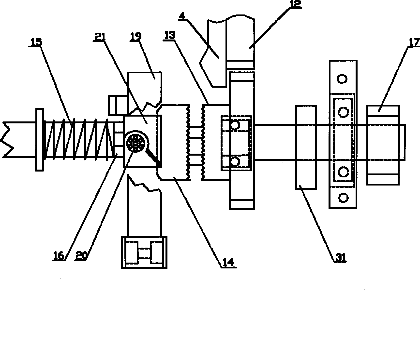
[0035] Embodiment 3, a fast and energy-saving automatic straightening and cutting machine, wherein: the shearing assembly includes a spur gear 12, a clutch assembly, a pinion 17, and a shearing gear 18; the disc gear 4 passes through the spur gear 12 and the clutch assembly in sequence 1. The pinion gear 17 drives the shearing gear 18; the shearing gear 18 drives the shearing knife that can cut off the wire. All the other are with embodiment 1 or 2.


PUM


Abstract

The invention relates to a fast and energy-saving automatic straightening cutting machine, which is mainly used for the automatic straightening and fixed-length stock cutting of linear materials such as reinforcing steel bars used in the construction field, and has the main structure as follows: a straightening drum is driven by an electric motor by a belt; simultaneously, the electric motor sequentially drives an angle tooth belt pulley, a rear axle angle gear, a plate gear and a front feeding main shaft by another belt; the front feeding main shaft drives a feeding assembly and a traction assembly; and the plate gear drives a cutting assembly. The straightening cutting machine has the advantages that: the rear axle angle gear is directly decelerated to drive the plate gear on the front feeding main shaft, and the gear on the main shaft simultaneously drives the gear transmission structure along which a clutch gear, an upper compress roller and a back feeding roller rotate simultaneously, thus reducing multistage speed change of the overall unit as well as the amount of a plurality of gears and shafts; the structure is extremely simple, the machine can work only needing one 5.5kW electric motor, and about 6 kilowatt-hours of electricity are needed for straightening and cutting one ton of reinforcing steel bars, thus extremely saving the electricity and energy.

Description

technical field [0001] The invention relates to an automatic straightening and cutting machine. In particular, it is a fast and energy-saving automatic straightening and cutting machine, which is mainly used for automatic straightening and fixed-length cutting of steel bars and other wires used on construction sites. Background technique [0002] In the previous patent application document "Automatic Wire Pulling Straightening and Shearing Equipment" declared by us, especially the combination of the patent application document figure 1 , it can be found that the specific details of how the motor 1 drives the straightening cylinder, the dynamic feeding assembly, the traction assembly, and the shearing assembly are not disclosed. [0003] At present, the CT4-12 and CT4-14 automatic wire straightening and cutting machines produced by our country's peer manufacturers generally have two control shearing methods, mechanical transmission gear shearing and oil pump hydraulic push s...

Claims


Application Information

Patent Timeline
Patent Type & Authority Applications(China)
IPC IPC(8): B21F1/02B21F11/00B21F23/00
Inventor 龙乐武龙琦
Owner 龙乐武
Why Eureka
Try Eureka