Clock generator based on phase-locked loop and clock generating method

A clock generator, phase-locked loop technology, applied in the direction of signal generation/distribution, automatic power control, electrical components, etc., can solve the problem of non-coverage, maximum frequency oscillation frequency limit, phase adjustment digital multiplexer accuracy limit, etc. problem, to achieve the effect of convenient adjustment and convenient phase

Active Publication Date: 2010-07-07
HISENSE VISUAL TECH CO LTD
View PDF3 Cites 2 Cited by
  • Summary
  • Abstract
  • Description
  • Claims
  • Application Information

AI Technical Summary

Problems solved by technology

[0005] However, the clock signal output by this kind of clock generator based on the phase-locked loop can only be divided by two or four of the output frequency of the PLL circuit, and the output frequency cannot cover every point in the output frequency range. , and its maximum frequency will be limited by the oscillation frequency of the PLL circuit, and the bandwidth is narrow
Therefore, when the electronic system is relatively complex, it is still impossible to obtain all the required clock frequencies by using the above-mentioned existing clock generator based on the phase-locked loop only by using a single crystal oscillator. Different oscillators and phase-locked loops to obtain the required clock signals of different frequencies
[0006] In addition, the above-mentioned existing clock generator based on phase-locked loop also has the problems that the number of output phases is limited by the number of phases generated by the PLL, the adjustment step of the output frequency is too large, and the phase adjustment is limited by the accuracy of the digital multiplexer.

Method used


Image

  • Clock generator based on phase-locked loop and clock generating method
  • Clock generator based on phase-locked loop and clock generating method
  • Clock generator based on phase-locked loop and clock generating method

Examples


no. 1 example

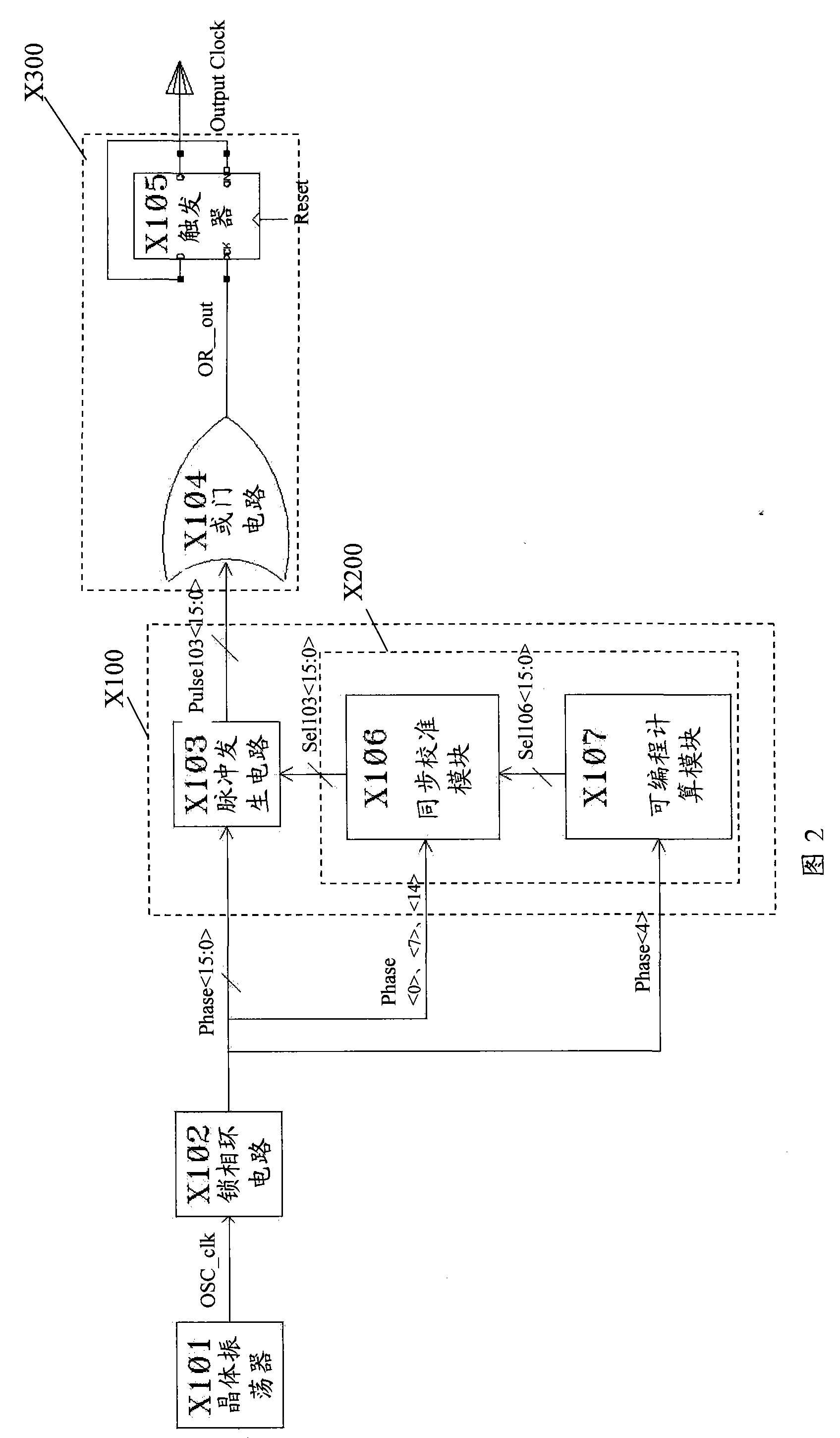
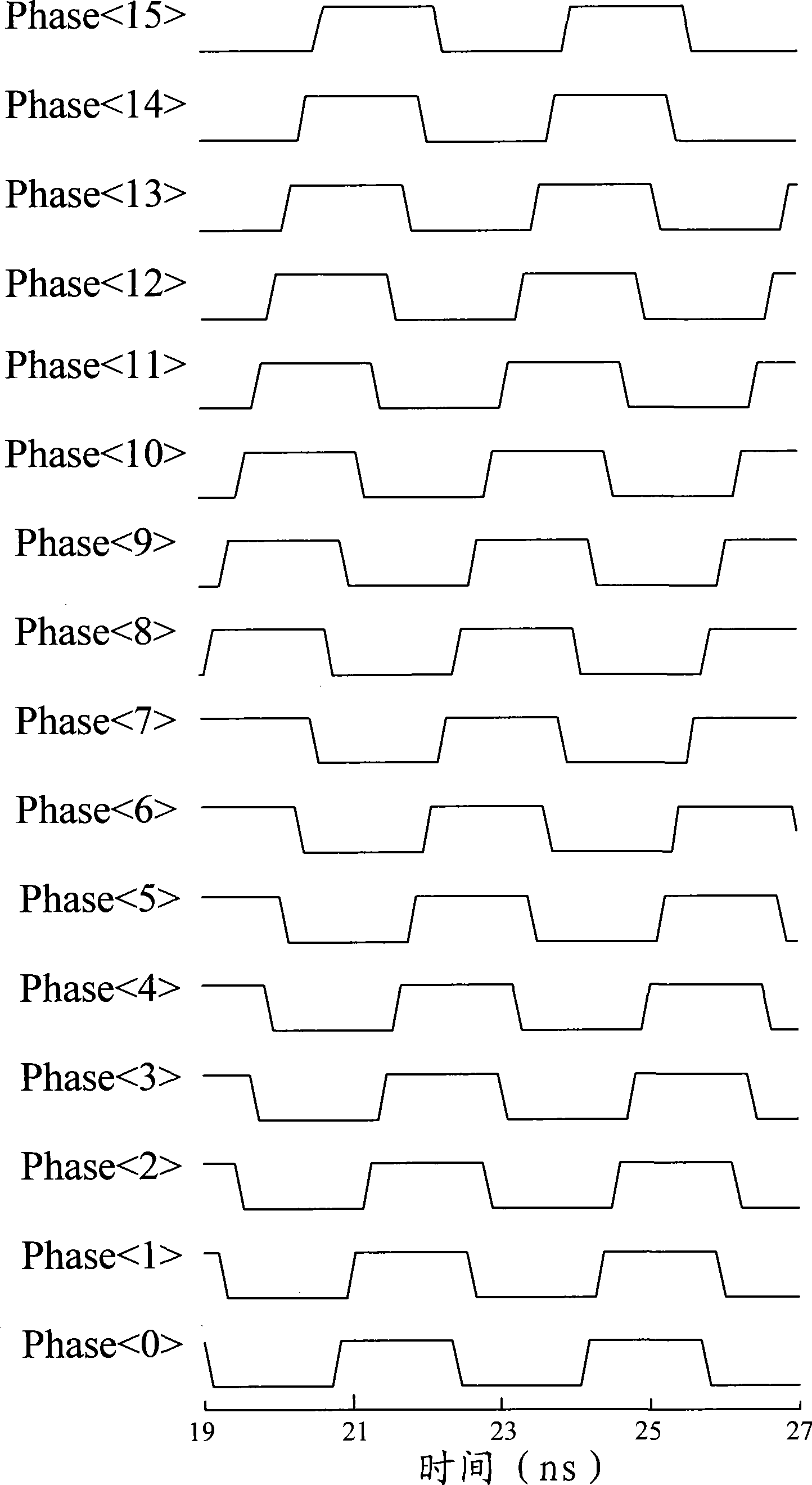
[0059] The first embodiment of the present invention details a clock generator based on a phase-locked loop. 2 is a schematic diagram of a clock generator based on a phase-locked loop in the first embodiment of the present invention, Figure 3 to Figure 10 It is the timing diagram inside the clock generator based on the phase-locked loop in the first embodiment of the present invention, below in conjunction with Fig. 2 to Figure 10 The first embodiment of the present invention will be described in detail.

[0060] As shown in Figure 2, the clock generator based on the phase-locked loop in the present embodiment includes: a crystal oscillator X101, which is used to output an initial clock signal (OSC_clk); a phase-locked loop circuit X102, which is used to receive the crystal oscillator The initial clock signal (OSC_clk) output by X101 outputs a plurality of first multi-channel clock signals with different phases (in this embodiment, 16 first multi-channel clock signals with ...

no. 2 example

[0120] The second embodiment of the present invention proposes a phase-locked loop-based clock generation method that can be realized by using the clock generator in the first embodiment of the present invention, Figure 11 It is a flowchart of a clock generation method based on a phase-locked loop in the second embodiment of the present invention, combined below Figure 11 and Figure 2 to Figure 10 The clock generation method based on the phase-locked loop in the second embodiment of the present invention is introduced in detail.

[0121] Step 1101: Output an initial clock signal by using a crystal oscillator.

[0122] An initial clock signal (OSC_clk) having a certain fixed frequency is generated by the crystal oscillator X101.

[0123] Step 1102: Using a phase-locked loop circuit to complexize the initial clock signal output by the crystal oscillator, and output a plurality of first multi-channel clock signals with different phases.

[0124] The initial clo...


PUM


Abstract

The invention discloses a clock generator based on a phase-locked loop, which comprises a crystal oscillator, a phase-locked loop circuit, a clock adjusting module and a doubling circuit output module, wherein the clock adjusting module is used for receiving a first multi-path clock signal output by the phase-locked loop circuit, respectively adjusts the frequency and the phase of each first multi-path clock signal according to the preset frequency and phase of a target clock signal, and outputs multiple second multi-path clock signals respectively corresponding to all of the first multi-pathclock signals; the doubling circuit output module is used for receiving and merging the second multi-path clock signals output by the clock adjusting module, and outputs the target clock signal with the preset frequency and phase. The invention also discloses a corresponding clock generating method. The clock generator based on a phase-locked loop and the clock generating method can conveniently and flexibly adjust the frequency and the phase of the output target clock signal, and greatly broaden the band width which can be realized.

Description

technical field [0001] The invention relates to the field of pulse generators, in particular to a phase-locked loop-based clock generator and a clock generation method. Background technique [0002] In an electronic system, the clock is equivalent to the heart, and the performance and stability of the clock directly determine the performance of the entire system. Currently, commonly used clock sources include a crystal oscillator (XO, also referred to as crystal oscillator) and a phase-locked loop (PLL) circuit. Among them, the crystal oscillator clock is usually only limited to work at one frequency, and the price of a more accurate crystal oscillator is relatively expensive. The phase-locked loop circuit is usually composed of a phase-frequency detector (PFD), a charge pump, a low-pass filter (LPF) and a voltage-controlled oscillator (VCO), because it can use a relatively cheap low-frequency crystal and has a wider frequency output range and higher design flexibility, an...

Claims


Application Information

Patent Timeline
Patent Type & Authority Patents(China)
IPC IPC(8): G06F1/08H03L7/06
Inventor 温带豪
Owner HISENSE VISUAL TECH CO LTD
Why Eureka
Try Eureka