
Intelligent duplicate power supply conversion switch

A dual-power conversion and dual-power switching technology is applied to electric switches, high-voltage/high-current switches, and power devices inside switches. Effects of cost reduction and high reliability

Inactive Publication Date: 2009-04-29
WENZHOU UNIVERSITY
View PDF0 Cites 2 Cited by
  • Summary
  • Abstract
  • Description
  • Claims
  • Application Information

AI Technical Summary

Problems solved by technology

[0003] The traditional dual power switching mechanism uses two high-voltage switch cabinets plus a set of extremely complicated electrical interlocking devices to prevent parallel operation of the two circuits
This kind of dual power supply device has the following three major defects: (1) Unreliable locking: At present, the reliability of electrical interlocking is too low, and it is strictly forbidden to use it. There is no unified design specification standard for mechanical interlocking devices, and it can only be designed and modified by each locality.
(2) The operation is complicated, and it is easy to jam, causing electric accidents; (3) The investment is large, and two switch cabinets need to be purchased, and then the locking device is designed, and then refitted to the switch cabinet
The advantage of the spring operating mechanism is that it does not require a high-power DC power supply, the motor power is small, AC and DC are dual-purpose, and it is suitable for AC operation; its disadvantage is that the structure is relatively complicated, the number of parts is large (about 200), and high processing accuracy is required. , the manufacturing process is complicated, the cost is high, and the reliability of the mechanism is not easy to guarantee
The advantages of the electromagnetic operating mechanism are simple structure, small number of parts (about 120), reliable operation, and low manufacturing cost, but its disadvantages are that the power consumed by the closing coil is too large, the pressure of the contacts is small, and the mechanism It is bulky and takes a long time to operate, requiring users to equip expensive battery packs, etc.

Method used


Image

  • Intelligent duplicate power supply conversion switch
  • Intelligent duplicate power supply conversion switch
  • Intelligent duplicate power supply conversion switch

Examples


Embodiment 1

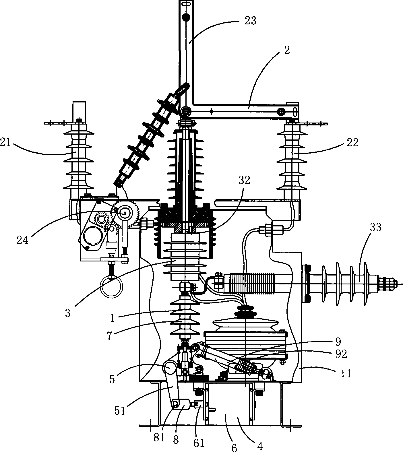
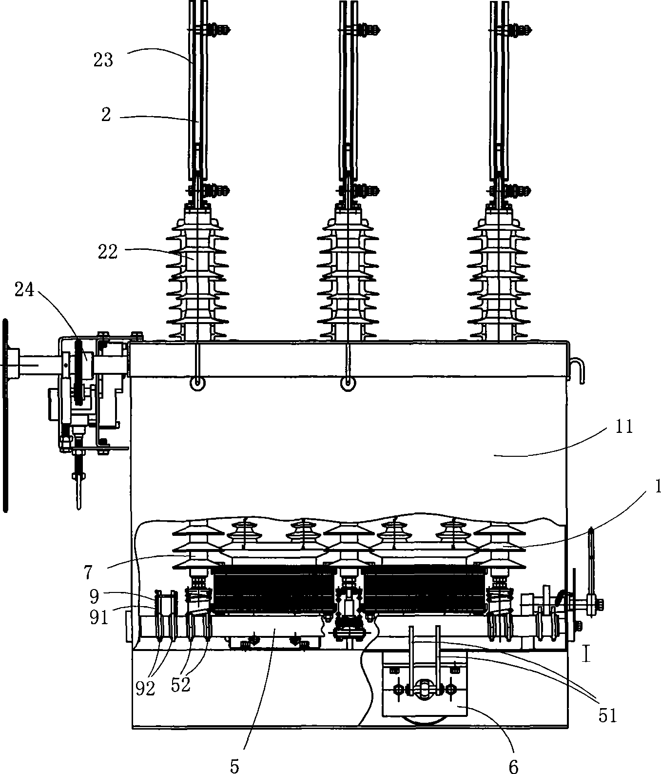
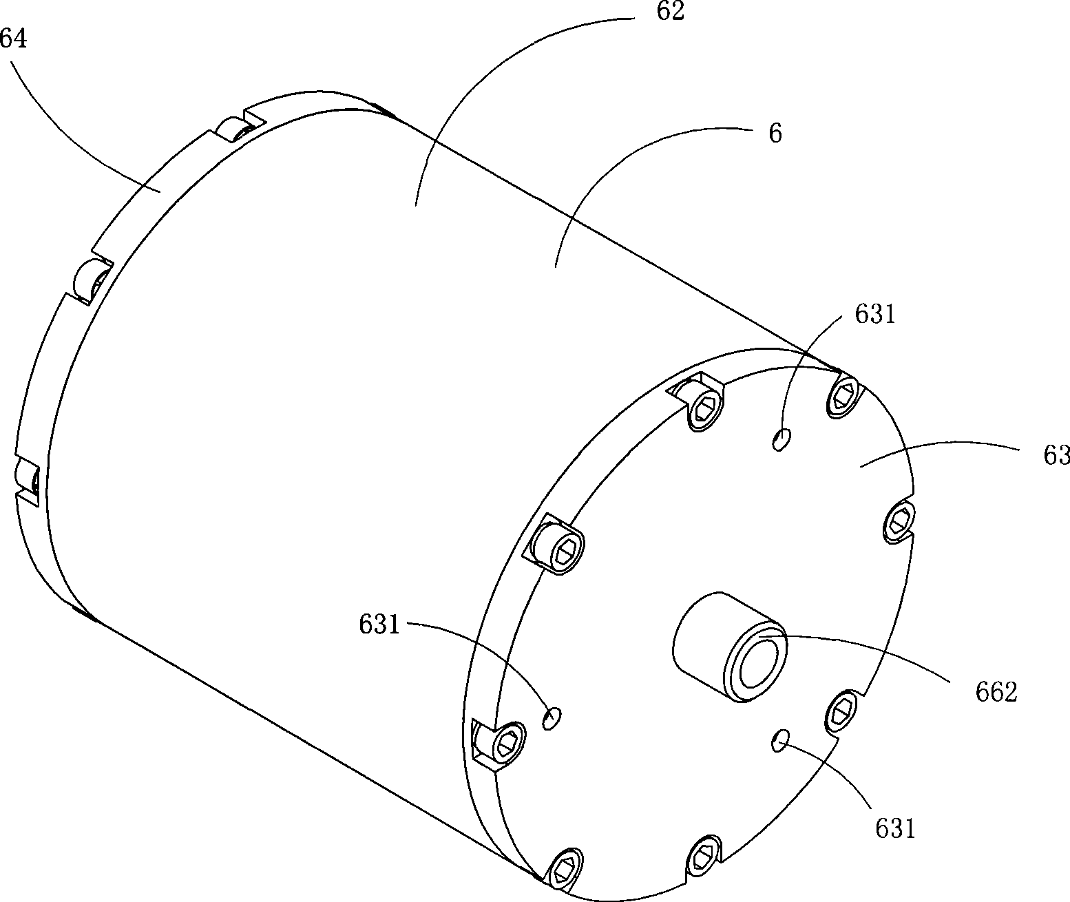
[0035] Figure 1 to Figure 7 A first embodiment of the invention is shown in which, figure 1 is a structural schematic diagram of the first structure of the present invention; figure 2 Yes figure 1 The structural diagram of the intelligent dual power transfer switch shown when viewed from another angle; image 3 Yes figure 1 A schematic diagram of a three-dimensional structure of the permanent magnet drive mechanism in the intelligent dual power transfer switch shown; Figure 4 Yes image 3 The schematic diagram of the structure of the permanent magnet drive mechanism when viewed from the direction of the front cover; Figure 5 Yes Figure 4 Sectional view along line A-A; Image 6 Yes image 3 A schematic diagram of a three-dimensional structure of the permanent magnet drive mechanism shown after removing the front cover; Figure 7 Yes image 3 A schematic diagram of a half-section structure of the permanent magnet drive mechanism shown after removing the permanent ...

Embodiment 2

[0047] Figure 8 It is a half-sectional structural schematic diagram of the permanent magnet drive mechanism used in the second structure of the present invention after the permanent magnet is removed, showing the second embodiment of the present invention.

[0048] This embodiment is basically the same as Embodiment 1, the difference is: see Figure 8 , the arrangement of the permanent magnets is different. In this embodiment, the inner wall of the housing 62 is provided with an annular groove 100 for limiting the permanent magnet 67 , and the permanent magnet 67 is disposed in the groove 100 . This structure enables the adjusting bolt to limit the yoke ring and at the same time limit the permanent magnet to avoid loosening and displacement due to vibration.

Embodiment 3

[0050] Figure 9 It is a schematic diagram of the half-section structure of the permanent magnet drive mechanism used in the third structure of the present invention after removing the permanent magnet, showing the third embodiment of the present invention.

[0051] This embodiment is basically the same as Embodiment 1, the difference is: see Figure 9 , the arrangement of the permanent magnets is different. In this embodiment, the outer wall of the yoke ring 68 is provided with an annular groove 100 for limiting the permanent magnet 67 , and the permanent magnet 67 is disposed in the groove 100 . This structure enables the adjusting bolt to limit the yoke ring and at the same time limit the permanent magnet to avoid loosening and displacement due to vibration.


PUM


Abstract

The invention discloses an intelligent double-power transfer switch which comprises a vacuum breaker body and a double-power switching unit; the vacuum breaker body comprises cushion mechanisms; a cushion crankarm is arrange on the main shaft of the switch; one end of a spring is connected with the shell of the switch and the other end is connected with the cushion crankarm; an arc extinguishing mechanism is vertically arranged; the main shaft of the switch is horizontally arranged; a permanent magnet drive mechanism is arranged at the central lower side or deviated to the right lower side of the main shaft of the switch; when the permanent magnet drive mechanism is arranged at the central lower side of the main shaft of the switch, the number of the cushion mechanisms is two and are respectively arranged at the two side ends of the main shaft of the switch; when the permanent magnet drive mechanism is deviated to the right lower side of the main shaft of the switch, the number of the cushion mechanism is one and is arranged at the left end of the main shaft of the switch; and an operation mechanism is a permanent magnet operation mechanism. The intelligent double-power transfer switch has the advantages of simpler structure, less fault sources and higher reliability.

Description

technical field [0001] The invention relates to the technical field of high-voltage switch structure design, in particular to an intelligent dual-power switch. Background technique [0002] In the power network, there are many users who have high requirements on the reliability of power supply, such as coal mines and oil refineries. Once a power outage occurs in these units, it will bring significant economic losses or even casualties to the unit. Therefore, the power supply in these units In the system, both the main power supply and the backup power supply are required. When the main power supply fails, the backup power supply must be put into power immediately to restore the power supply. In order to achieve this purpose, it is necessary to manually switch between the main power supply and the backup power supply through a dual power supply switching mechanism. or switch automatically. [0003] The traditional dual power switching mechanism uses two high-voltage switch c...

Claims


Application Information

Patent Timeline
Patent Type & Authority Applications(China)
IPC IPC(8): H01H3/28H01H33/66H01H33/38
Inventor 叶忻泉
Owner WENZHOU UNIVERSITY
Learn More