High precision time difference calibrating method based on FPGA

A calibration method and high-precision technology, applied in the direction of clock driven by synchronous motor, electronic timer, automatic power control, etc., can solve the problem of not giving detailed time difference processing algorithm, no algorithm implementation scheme and design introduction, implementation scheme There are no problems with the introduction and the algorithm, which achieves the effects of fast synchronization between satellites, reduced injection frequency, and strong real-time performance.

Active Publication Date: 2009-04-29
中国航天科技集团公司第五研究院第五〇四研究所
View PDF0 Cites 26 Cited by
  • Summary
  • Abstract
  • Description
  • Claims
  • Application Information

AI Technical Summary

Problems solved by technology

[0005] The time difference calibration technology learned from public publications and public channels is as follows: First, adopt phase-locked loop / frequency-locked loop phase modulation technology and timing technology, realize time difference calibration through software, phase-locked loop / frequency-locked loop phase modulation technology It is already relatively mature, and can obtain high-precision phase modulation accuracy, but the phase-locked loop / frequency-locked loop phase modulation technology requires two input signals (one local signal, one reference signal); the other is to use phase modulation technology to achieve The time is relatively synchronized (regardless of the absolute time difference), but the specific implementation scheme and algorithm are not described in the introduction
[0006] The deficiencies of existing literature at home and abroad are: (1) no detailed time difference processing algorithm, especially the introduction of the algorithm for simultaneous calibration of absolute time difference and relative time difference; (2) no introduction of specific implementation schemes and designs of related algorithms

Method used


Image

  • High precision time difference calibrating method based on FPGA
  • High precision time difference calibrating method based on FPGA
  • High precision time difference calibrating method based on FPGA

Examples


Embodiment Construction

[0031] Below in conjunction with accompanying drawing and specific embodiment the present invention is described in further detail:

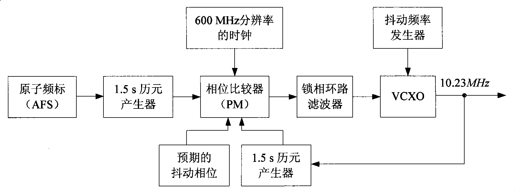
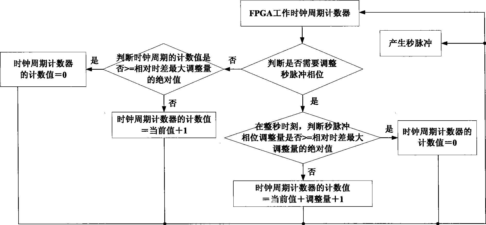
[0032] The FPGA externally inputs a working clock, and another device has a clock with a different source and the FPGA working clock, there is a time difference Δt between them, and this time difference needs to be adjusted under certain application conditions. The present invention adopts the main processing chip based on FPGA The hardware platform can calibrate this time difference by using a high-precision time difference calibration method based on FPGA.

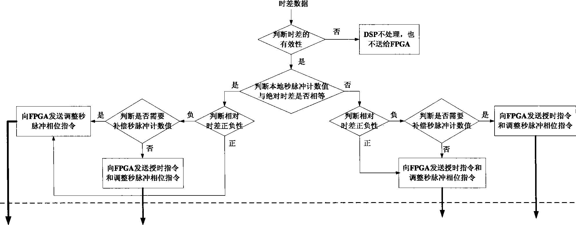
[0033] Here we first explain several concepts and the method of judging the validity of time difference.

[0034] Time difference Δt: refers to the difference between the local time and the reference time Δt=ΔTs+ΔTp, including the absolute time difference ΔTs and the relative time difference ΔTp, the absolute time difference ΔTs refers to the count value of the second pulse, and the relati...


PUM


Abstract

The present invention relates to an absolute time difference processing algorithm that is a high-precision time calibration method based on FPGA by using a prevalent processor FPGA chip, especially relates to a high-precision clock source leading phase processing algorithm. The present invention can realize a relative time difference calibration and an absolute time difference calibration at the same time by using a high-accuracy clock source leading phase processing algorithm, the main time difference calibration algorithm is performed by FPGA, leading phase time difference especially the time difference leading up by one FPGA working clock period is converted into a legging time difference through the cooperation of DSP and is performed with an on-second calibration by a FPGA to obtain high-accuracy time reference pulses and a time thereof, before the calibration of leading time difference of which the absolute value is smaller than a period of time reference pulses, time and reference time synchronization can be realized, therefore, the method has characteristics of reduced ground injection frequency, fast inter-constellation synchronization and high real-time performance, and realizes the constellation time synchronization.

Description

technical field [0001] The invention relates to a high-precision time difference calibration method, in particular to an FPGA-based high-precision time difference calibration method, which is mainly used for high-precision time difference calibration. Background technique [0002] At present, in the ground time system, the time management in the satellite constellation, and the time synchronization system between the satellite and the ground, almost all of them need to be calibrated for the time difference. The calibration of time difference is applied in many time systems at home and abroad, and the most widely used is the time service system recognized by various countries and even internationally, but there is no public literature that introduces the time difference processing algorithm in detail. [0003] "Measurement and Calibration of GPS Fundamental Frequency Standard" published in Volume 27, Issue 5 of "Aerospace Measuring Technology" in October 2007 introduced a com...

Claims


Application Information

Patent Timeline
Patent Type & Authority Applications(China)
IPC IPC(8): H03L7/00H03L7/06G04G7/00
Inventor 钟兴旺韩虹吴化军张赤萍陈思宏
Owner 中国航天科技集团公司第五研究院第五〇四研究所
Why Eureka
Try Eureka