
Inlet distortion and recovery control system

A control system, air entry technology, applied in the direction of charging system, aircraft control, engine control, etc., can solve the problems of inefficiency, complex aircraft weight and/or volume, unadjustable, etc.

Inactive Publication Date: 2009-04-29
THE BOEING CO
View PDF0 Cites 7 Cited by
  • Summary
  • Abstract
  • Description
  • Claims
  • Application Information

AI Technical Summary

Problems solved by technology

unfortunately, these systems are complex and can add significant weight and / or volume to the aircraft
Also, they are optimized for one flight condition or throttle setting and are not adjustable
they become less efficient at different speeds, altitudes, angles of attack or sideslip, and engine air flow rates

Method used


Image

  • Inlet distortion and recovery control system
  • Inlet distortion and recovery control system
  • Inlet distortion and recovery control system

Examples


Embodiment Construction

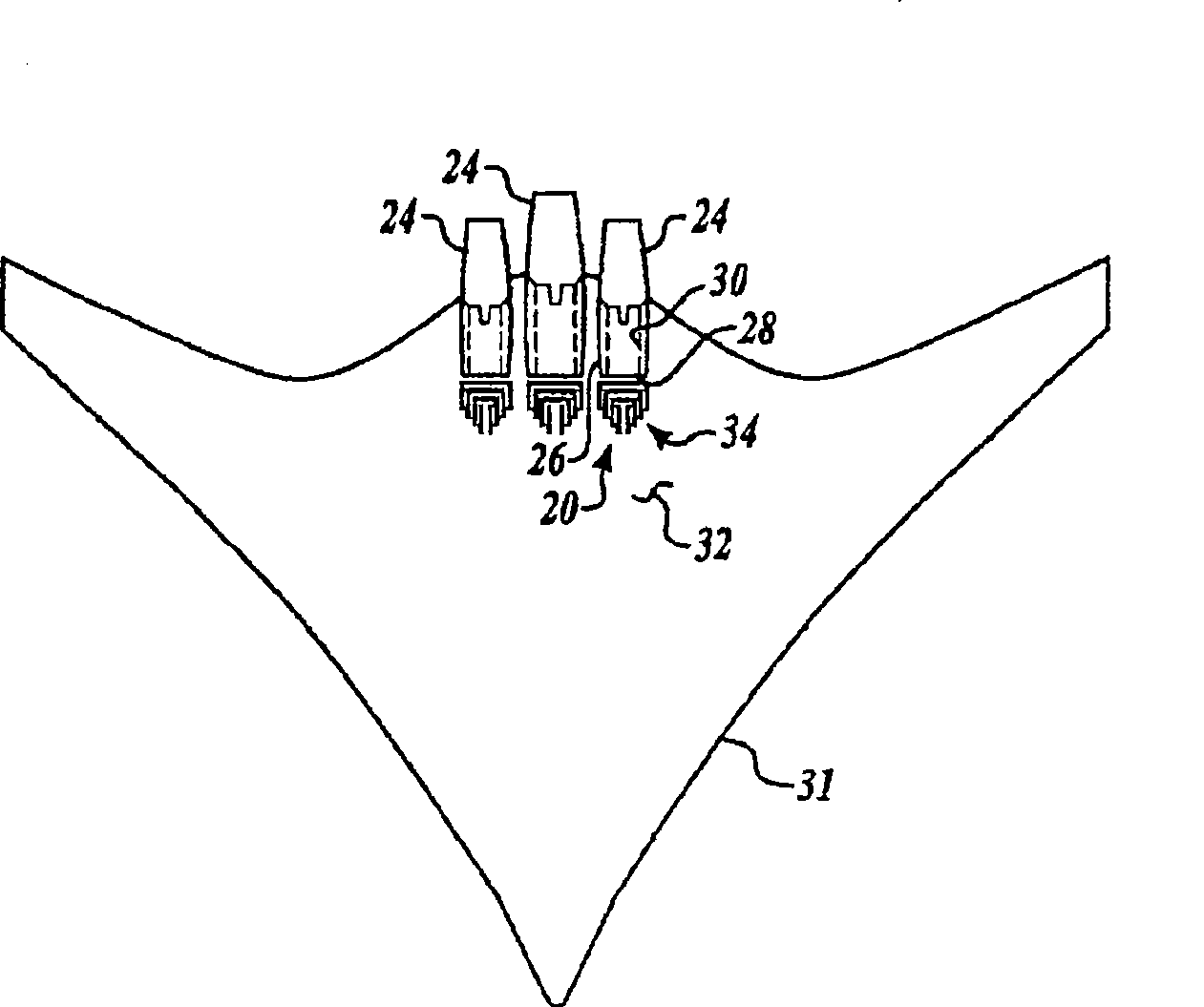
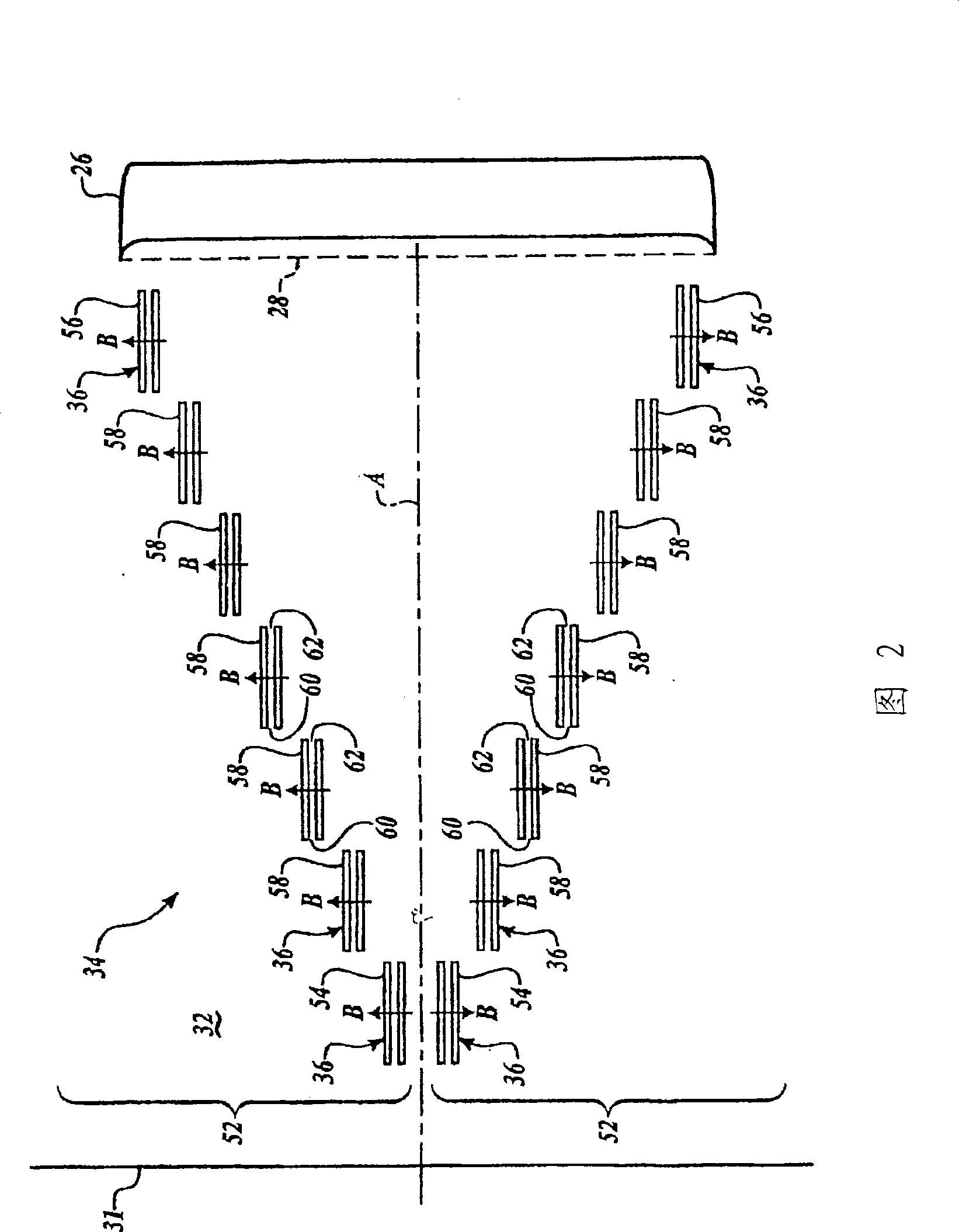
[0025] by reference Figure 1A and 1B And to describe generally, the exemplary air intake system 20 is installed on an aircraft 22 to minimize or, in some cases, eliminate boundary layers and thereby provide improved quality intake air to corresponding engines 24 . The system 20 can be tuned to meet propulsion and power demands across the entire aircraft hull more efficiently than prior art techniques at various speeds, altitudes, and angles of attack or sideslips. although Figure 1A and 1B While the aircraft 22 is shown as a hybrid wing-like body with the engine at the rear, it is understood that the system 20 may take the form of any machine capable of flying in the atmosphere, including but not limited to tubular and winged aircraft, commercial transport aircraft, private jets, missiles, rotorcraft or unnamed aircraft. The system 20 may be used for the inlet or inlet of any component, including not only the propulsion engine 24 but also an auxiliary power unit (not shown...


PUM


Abstract

An air induction system for an aircraft to control distortion and pressure recovery for improved aerodynamic performance. The system includes an inlet and at least one dielectric barrier discharge generator positioned upstream of the engine for imparting momentum to a low-energy boundary layer of air. A plurality of spaced dielectric barrier discharge generators may be activated in selected combinations to optimize performance at respective flight conditions. In one embodiment, one or more generators may be oriented generally transverse relative to the flow of intake air to eject the boundary layer in a lateral direction and prevent its ingestion by the engine. In another embodiment, one or more generators may be oriented along the direction of flow to accelerate the boundary layer air.

Description

Background technique [0001] During flight, a boundary layer of low energy air forms on the surface of the aircraft. The boundary layer is a thin film of low velocity, low dynamic pressure air near the solid boundary due to stationary air along the solid boundary. Boundary layers that form on surfaces located upstream of the engine can be ingested by the engine and reduce overall pressure recovery and corresponding propulsion performance. In turn, the ingested boundary layer reduces distortion (ie, a measure of the quality or uniformity of flow characteristics) and thereby reduces the stability of engine operation. [0002] These problems are exacerbated for intake air, which requires the airflow to undergo any significant turn in flow direction. The turning creates large pressure gradients as well as secondary flows, which increase the thickness of the boundary layer or cause it to separate from the surface. [0003] The boundary layer is particularly prone to detachment fr...

Claims


Application Information

Patent Timeline
Patent Type & Authority Applications(China)
IPC IPC(8): B64C21/00F02C7/047B64C23/00
CPCF02C7/04B64D2033/0286F02C7/057F01D5/145Y02T50/671B64D2033/0226Y02T50/673B64D33/02F05D2270/172Y02T50/60
Inventor 约瑟夫·S·西尔基克里斯托弗·D·威尔逊理查德·S·戴尔
Owner THE BOEING CO
Learn More