
Concrete box girder bridge widening and reinforced structure and construction method thereof

A concrete box girder and reinforcement structure technology, applied in bridge reinforcement, bridge, bridge maintenance, etc., can solve the problems of unable to restrain the occurrence and development of oblique cracks in the web, increase the self-weight, and construction difficulties, so as to avoid damage to the natural environment and adverse social impact, reducing lateral control stress, simple and convenient construction method

Inactive Publication Date: 2009-05-06
CHONGQING JIAOTONG UNIVERSITY
View PDF0 Cites 42 Cited by
  • Summary
  • Abstract
  • Description
  • Claims
  • Application Information

AI Technical Summary

Problems solved by technology

Due to the low traffic volume and vehicle load in the early stage, coupled with various reasons such as limited economy, the design width of box girder bridges is usually not large. The capacity and bearing capacity are obviously insufficient, which hinders economic development, and cracks of different natures will appear in the box girder, which affects the bearing safety and durability of the bridge structure
If the original box girder bridge is demolished to build a new bridge, it will require a lot of construction costs, resulting in a waste of manpower and material resources. Due to the long construction period, it will affect the traffic on the original road and hinder economic development; due to the demolition of the original bridge, a large amount of waste residue will be generated. Removing the piled up waste requires a large area, which is not conducive to environmental protection
[0003] In order to solve the above problems, methods of strengthening and widening the box girders of old bridges have emerged. The effective reinforcement methods are mainly to increase the cross-sectional area of ​​the box girder, paste steel plates, paste fiber layers, set prestressed beams in the body, add longitudinal steel plates in the box or increase Laterally stiffened steel frames, etc., can improve the local or overall mechanical performance of the bridge structure to a certain extent, but there are also some limitations or deficiencies. For example, increasing the cross-sectional area of ​​the box girder will cause great damage to the original structure and make construction difficult. , increased self-weight, new and old structure expansion or shrinkage inconsistencies affect the combination and other shortcomings; paste steel plates have the disadvantages of not being able to improve the overall resistance of the box girder structure and damage the original structure by high-density planting bars; setting internal prestressed beams has complex construction and damage to the original structure. The thin-walled box girder structure may cause new secondary diseases, damage the original structure, and increase local self-weight; the addition of longitudinal steel webs in the box has the disadvantages of large steel consumption, extremely difficult construction, and poor adaptability; The stiffened steel frame does not significantly improve the longitudinal stress of the box girder, and cannot inhibit the occurrence and development of oblique cracks in the web

Method used


Image

  • Concrete box girder bridge widening and reinforced structure and construction method thereof
  • Concrete box girder bridge widening and reinforced structure and construction method thereof
  • Concrete box girder bridge widening and reinforced structure and construction method thereof

Examples


Embodiment Construction

[0028] In this embodiment, the original box girder bridge is used for expressways and is divided into two parallel bridges.

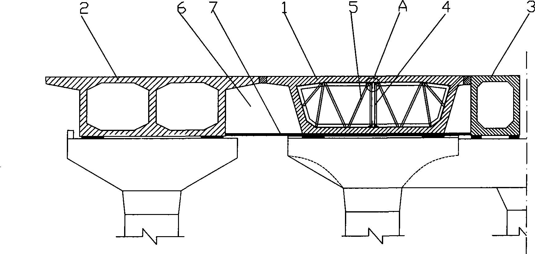
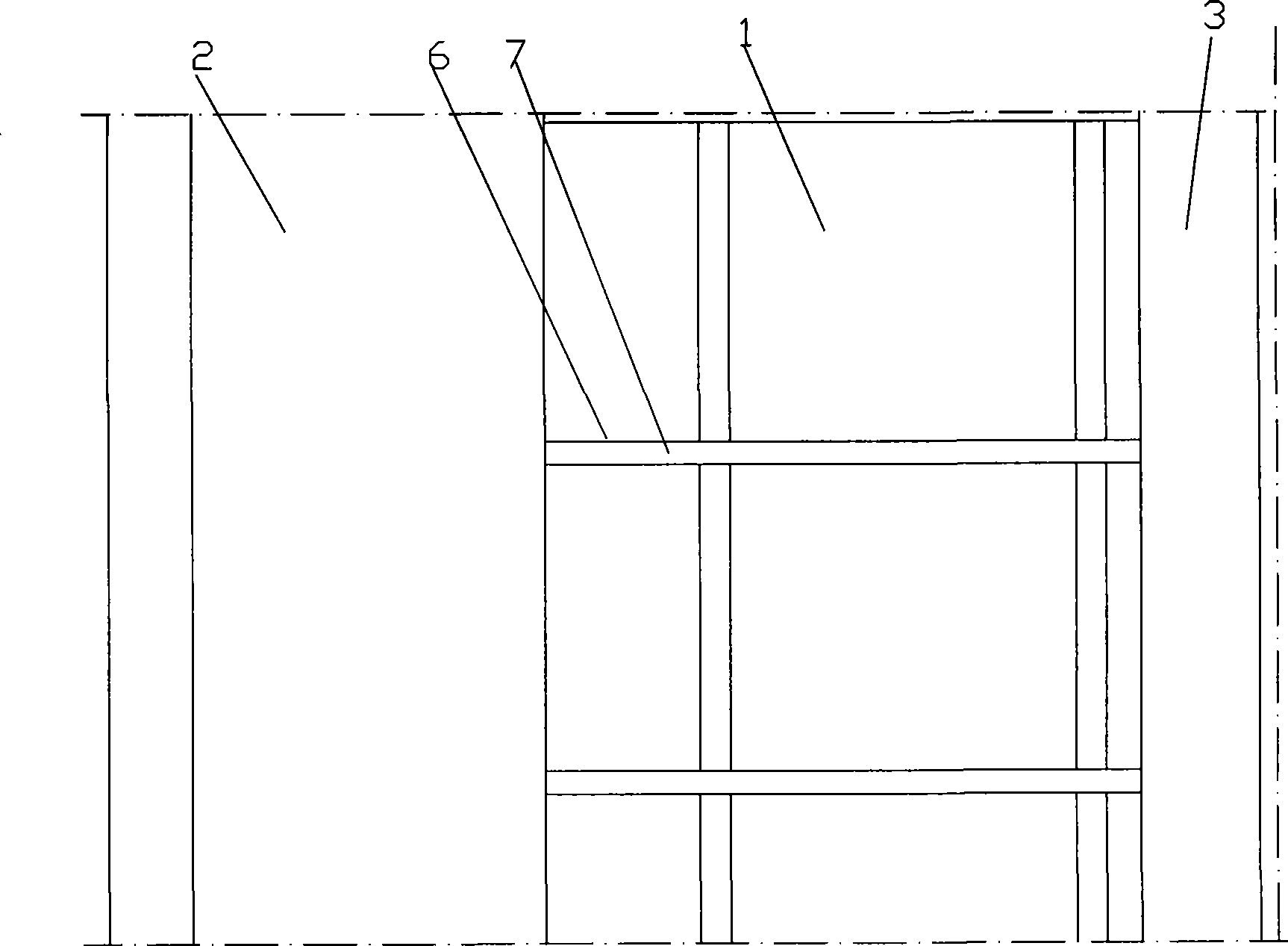
[0029] figure 1 It is a schematic diagram of the structure of the present invention, figure 2 It is the bottom view of the new box girder and the box girder of the original box girder bridge. Figure 3 is a schematic diagram of the longitudinal steel truss structure, and Figure 4 is a schematic layout diagram of the longitudinal steel truss structure and the horizontal steel truss structure. Figure 5 for figure 1 Enlarged view at A, the widened and reinforced concrete box girder bridge structure of this embodiment includes new box girder I2 and new box girder II3 parallel to the original box girder bridge 1 and located on both sides of the original box girder bridge 1, and the wings of the new box girder I2 The flange and the flange of the new box girder II3 are rigidly connected with the box girder flange of the original box girder bridge 1 by casti...


PUM


Abstract

The invention discloses a widening and reinforcing structure for a concrete box girder bridge and a method for constructing the same. The widening and reinforcing structure comprises a new box girder I and a new box girder II which are parallel with the original box girder bridge and are positioned at two sides of the original box girder bridge; and the box girder of the new box girder I and the box girder of the new box girder II are in rigid connection with box girder flanges of the original box girder bridge. The new box girders share part of the load of the original box girder so that the internal force and the deformation (or the stress of a control point) of a controlled cross section of the original box girder bridge are reduced by about 20 percent; and the generation and the development of cracks on a crest slab, a bottom plate and a web plate of the original box girder bridge can be effectively inhibited. The widening and reinforcing structure is simple, has slight damage to the original box girder bridge, and does not increase obvious structure deadweight substantially. The method for widening and reinforcing constructions is simple and convenient; the reinforced concrete box girder bridge has a reliable structure; the construction period is relatively short; the impact on the road traffic is relatively small; and the damage to the natural environment and the bad social impact caused by the demolition of an old bridge are avoided, thus the method has good comprehensive technical, economic and social benefits.

Description

technical field [0001] The invention belongs to the field of building structures and road engineering, in particular to a concrete box girder bridge widening and strengthening structure and a construction method thereof. Background technique [0002] Concrete box girder bridge is one of the more common bridge types, which has a simple structure, convenient construction and easy maintenance. Due to the low traffic volume and vehicle load in the early stage, coupled with various reasons such as limited economy, the design width of box girder bridges is usually not large. The capacity and bearing capacity are obviously insufficient, which hinders the development of the economy, and cracks of different natures will appear in the box girder, which affects the bearing safety and durability of the bridge structure. If the original box girder bridge is demolished to build a new bridge, it will require a lot of construction costs, resulting in a waste of manpower and material resour...

Claims


Application Information

Patent Timeline
IPC IPC(8): E01D22/00E01D2/04
Inventor 周志祥
Owner CHONGQING JIAOTONG UNIVERSITY
Learn More