

Polyphase fluid experimental tank system
A technology of multiphase flow and water inlet system, applied in the field of hydraulic multiphase flow research and water environmental protection, to achieve the effect of easy recovery and treatment, reduction of test water consumption and test cost, and easy observation
Inactive Publication Date: 2009-05-06
SICHUAN UNIV
View PDF0 Cites 38 Cited by
- Summary
- Abstract
- Description
- Claims
- Application Information
AI Technical Summary
Problems solved by technology
[0006] The purpose of the present invention is aimed at the defects existing in the prior art, and proposes a new type of multiphase flow test tank system for studying the problem of reservoir sediment density flow, the problem of pollutant migration and diffusion, and the demonstration of hydraulic experiments.
Method used
View moreImage
Smart ImageViewing Examples

Examples
Embodiment
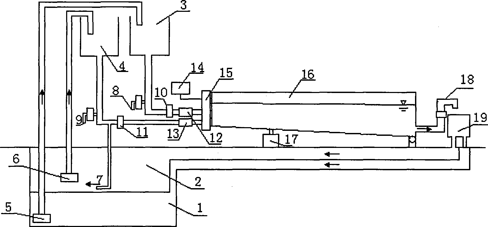
[0050] The glass water tank of the water tank main body used in the present embodiment is 1m high and 20m long.
Login to View More PUM
 Abstract
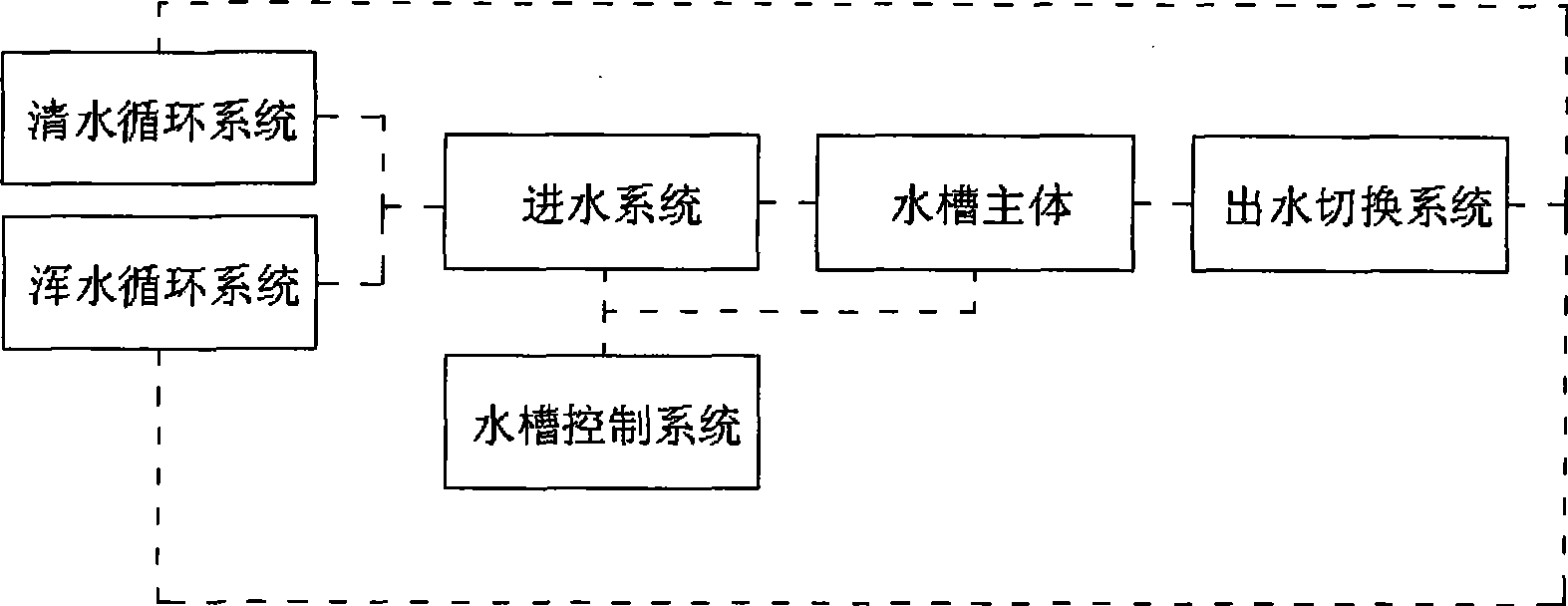
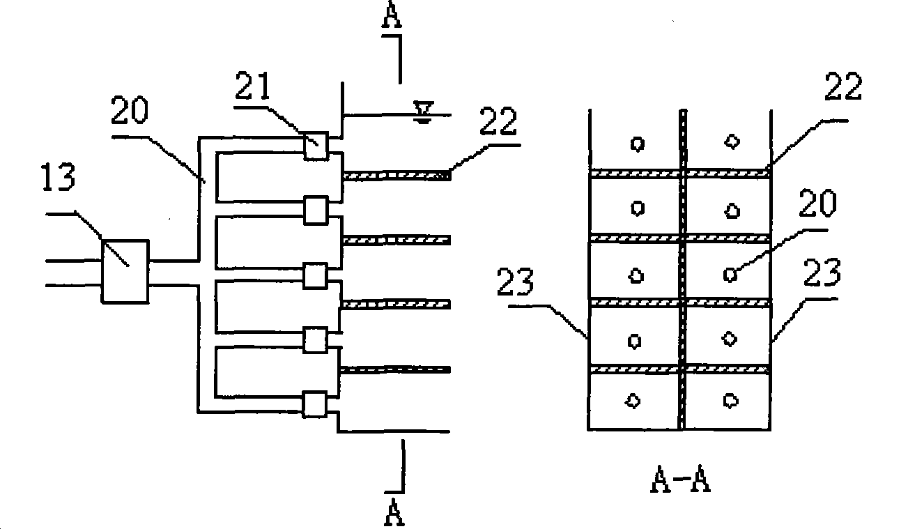
The invention relates to a multiphase flow test flume system which comprises a main body, a clear water circulating system, a muddy water circulating system, a water inlet system, a control system and a water outlet switching system, wherein a support and a jack are arranged at the bottom of the main body and are fixed on the ground by supporting hinges for adjusting the width and the gradient of a flume, and the water inlet system comprises a sampling discharge outlet, a manual valve, a flowmeter and an electromagnetic valve and is connected with the top end of the main body; the control system is arranged at one side of the top end of the main body for controlling all switches, and the water outlet switching system is arranged at one outer side end of a water outlet of the main body and is connected with a clear underground water pool in the clear water circulating system and a muddy underground water pool in the muddy water circulating system. Due to the clear water circulating system and the muddy water circulating system which are independent, the invention reduces test water consumption and test cost and conveniently recycles and treats polluted water samples, and a clear water / muddy water switching device of a water outlet system is easily designed and conveniently operated so as to effectively solve the switching problem among different circulating systems.
Description
technical field [0001] The invention relates to hydraulic multiphase flow research and water environment protection technology, in particular to a multiphase flow test water tank system for reservoir sediment density flow problem in water conservancy and hydropower engineering design research. Background technique [0002] Multiphase flow refers to a mixture of two or more phases that are incompatible or have phase interface substances. It is a discipline that studies the mixed flow of gaseous, liquid and solid substances. "Phase" refers to different physical properties or mechanical states of different states of matter or the same state of matter. In energy, water conservancy, chemical industry, metallurgy and other industrial sectors, as well as meteorology, biology, aerospace and other fields, problems involving multiphase flow are involved. With the increasing intensity and speed of water resources development and utilization in recent years, and people's increasing awa...
Claims
Login to View More Application Information
Patent Timeline
 Patent Type & AuthorityApplications(China)
IPC IPC(8): G01M10/00
Inventor李嘉易文敏李克锋李然邓云安瑞冬
OwnerSICHUAN UNIV