Bobtail tension rivet and riveting method

A technology of pulling rivets and short tails, applied to rivets and other directions, can solve the problems of complex structure and system of rotary riveters, long riveting time of pulling rivets, large riveting space, etc., and achieve fast riveting speed, reduced riveting steps, and good installation Effect

Inactive Publication Date: 2009-05-13
CRRC MEISHAN
View PDF1 Cites 8 Cited by
  • Summary
  • Abstract
  • Description
  • Claims
  • Application Information

AI Technical Summary

Problems solved by technology

[0004] But the above-mentioned 'pull rivet' (ZL200520035325X) has the following disadvantages: i. The ring groove section has a separation groove and a longer pull rod at the rear end, which requires a large riveting space, which is not conducive to the installation of rivets in a narrow space
But this pull rivet has the following problems: ①The end of the pull rivet rod is a threaded section, which must be used in conjunction with a special rotary riveter, and the structure and system of the rotary riveter are complicated, not only a conventional hydraulic system, but also a pneumatic device, Heavy and inconvenient to operate
③The riveting time of reusable rivets is longer

Method used


Image

  • Bobtail tension rivet and riveting method
  • Bobtail tension rivet and riveting method
  • Bobtail tension rivet and riveting method

Examples


Embodiment 1

[0039] Example 1: See Figure 1- Figure 6 ,

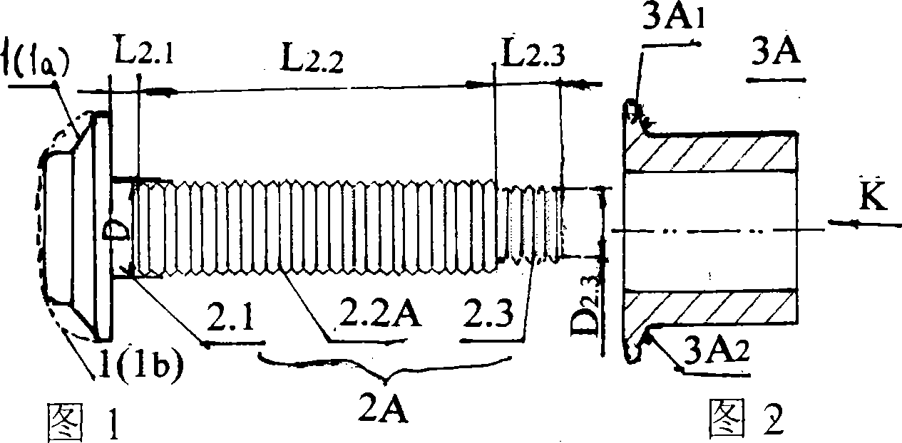
[0040]See Fig. 1, the short-tail pull rivet of 'ring groove riveting', nail shank 2A ​​has polished rod section 2.1, ring groove section 2.2A and short thin ring groove section 2.3. Generally, due to processing requirements, there is a processing transition section between the polished rod section 2.1 and the ring groove section 2.2A; a step needs to be processed between the ring groove section 2.2A and the short thin ring groove section 2.3. The length L of the short thin ring groove segment 2.3 2.3 The value range is 11.1-14.8mm, corresponding to the marked diameter D 2.3 The value range is 11.6-20.0mm, usually the length L of the short thin ring groove segment is 2.3 2.3 and diameter D 2.3 The selection is designed according to the tension of the riveter 6, the structure and size of the chuck 6.1.

[0041] See Figure 2- image 3 , the inner hole of the collar 3A is a light hole, and the size of the collar 3A matches the rin...

Embodiment 2

[0048] Example 2: See Figure 7- Figure 12 'Thread riveted' stub rivets.

[0049] As shown in Fig. 7, the structure of the nail rod 2B in embodiment 2 is different from that in Fig. 1 in embodiment 1 as follows: the threaded segment 2.2B is used to replace the ring groove segment 2.2A. The remaining nail heads, polished rod section 2.1 and short thin ring groove section 2.3 are all the same.

[0050] See Figure 8 , The structure of the collar 3B in Embodiment 2 is different from that in Figure 2 of Embodiment 1 as follows: a threaded segment 3B3 is provided at the rear port of the inner hole of the collar 3B. The front end of the collar 3B has the same disc 3B1 as in Embodiment 1 and a detection point 3B2 on the rear end of the disc.

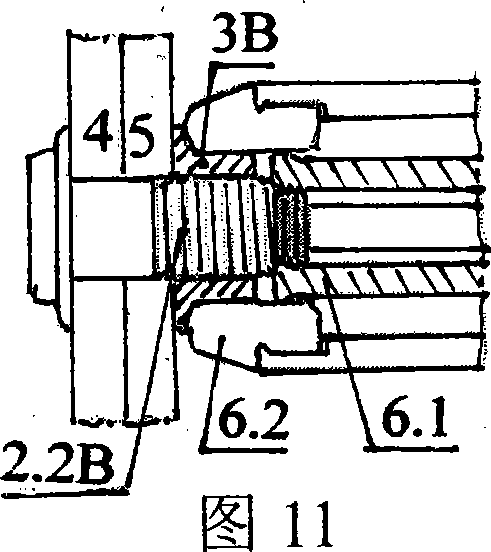
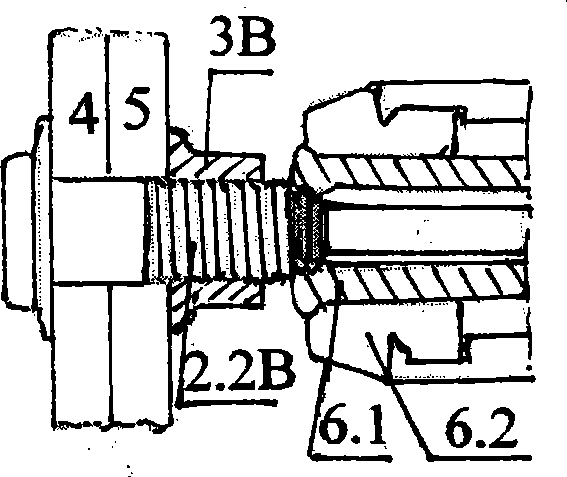
[0051] For the riveting steps of 'thread riveting' short tail rivets, see Figure 9 , Figure 10, Figure 11 and Figure 12 , where Figure 10, Figure 11 and Figure 12 The second step, the riveting step (ii) and the riveting step (iii) of t...


PUM


Abstract

The invention discloses a short-tail tension rivet and a riveting method thereof. The tension rivet consists of a rivet head, a rivet rod and a sleeve ring. The rivet rod is provided with a feed rod section, a ring groove section which is extruded and matched with the sleeve ring, and a short and thin ring groove section clamped by a riveting device collet from the front to the back. Compared to the prior tension rivet, a separating groove on the rear end of the tension rivet and a groove section tension rod are removed, so that the rivet rod is shortened and the material is saved by one third; when the rivet is riveted, the separating groove can not be broken; the riveting steps are reduced from the prior four steps to three steps, and the riveting is accelerated; and riveting can not cause impact, and the assembling place has no noise. If the prior same riveting device and the riveting stroke are adopted, the length of the ring groove section or a thread section can be lengthened correspondingly, so that rivets with the same specification can be applied to multiple riveting thicknesses, and the range of application is widen. The rear end of an inner hole of the sleeve ring for thread riveting is provided with a small section of screw thread; before the start of the riveting device, the sleeve ring is rotated manually and moved advance on the screw thread section, and positioned and sleeved on the screw thread section, so that when the riveting device is operated by operating staff for next step, the sleeve ring is not required to be held manually, and further the rivet is riveted relaxedly, conveniently and quickly. The screw thread and the groove riveting can be selected according to occasions.

Description

[0001] (1) Technical field: the short tail rivet and the riveting method of the present invention belong to the category of fasteners (F16B). (two) background technology: [0002] For a long time, steel structures such as railway wagons, automobiles, and bridges have used hot riveted ordinary rivets, whose chemical composition and mechanical properties are equivalent to 4.8-grade bolts, resulting in low connection reliability of the steel structure, short maintenance cycle, and post-maintenance costs. High-level problems, unable to meet the requirements of "heavy load and speed increase" of freight. And hot rivet installation labor intensity is big, and voice is big, pollutes environment. Therefore, it is very urgent and necessary to adopt new fasteners in the key and key parts of the above-mentioned steel structure. [0003] Chinese patent discloses a new type of fastener 'blind rivet' (ZL200520035325X, reference document 1) which solves the above problems and produces the f...

Claims


Application Information

Patent Timeline
Patent Type & Authority Applications(China)
IPC IPC(8): F16B19/08B21J15/02
CPCB21J15/022
Inventor 肖颖伏凯胡方年刘宇
Owner CRRC MEISHAN
Why Eureka
Try Eureka