Wire break detecting device for wire electric discharge machine

A technology for detection of electric spark wires and broken wires, which is applied in the direction of measuring devices, electrode manufacturing, circuits, etc., can solve problems such as fluctuations and achieve the effect of reducing consumption

Inactive Publication Date: 2009-05-20
FANUC LTD
View PDF2 Cites 6 Cited by
  • Summary
  • Abstract
  • Description
  • Claims
  • Application Information

AI Technical Summary

Problems solved by technology

However, in this technology, when the test voltage is superimposed on the machining voltage, a potential gradient is generated in the wire electrode, so there is a possibility that the machining result may be affected by fluctuations, etc.

Method used


Image

  • Wire break detecting device for wire electric discharge machine
  • Wire break detecting device for wire electric discharge machine
  • Wire break detecting device for wire electric discharge machine

Examples


Embodiment Construction

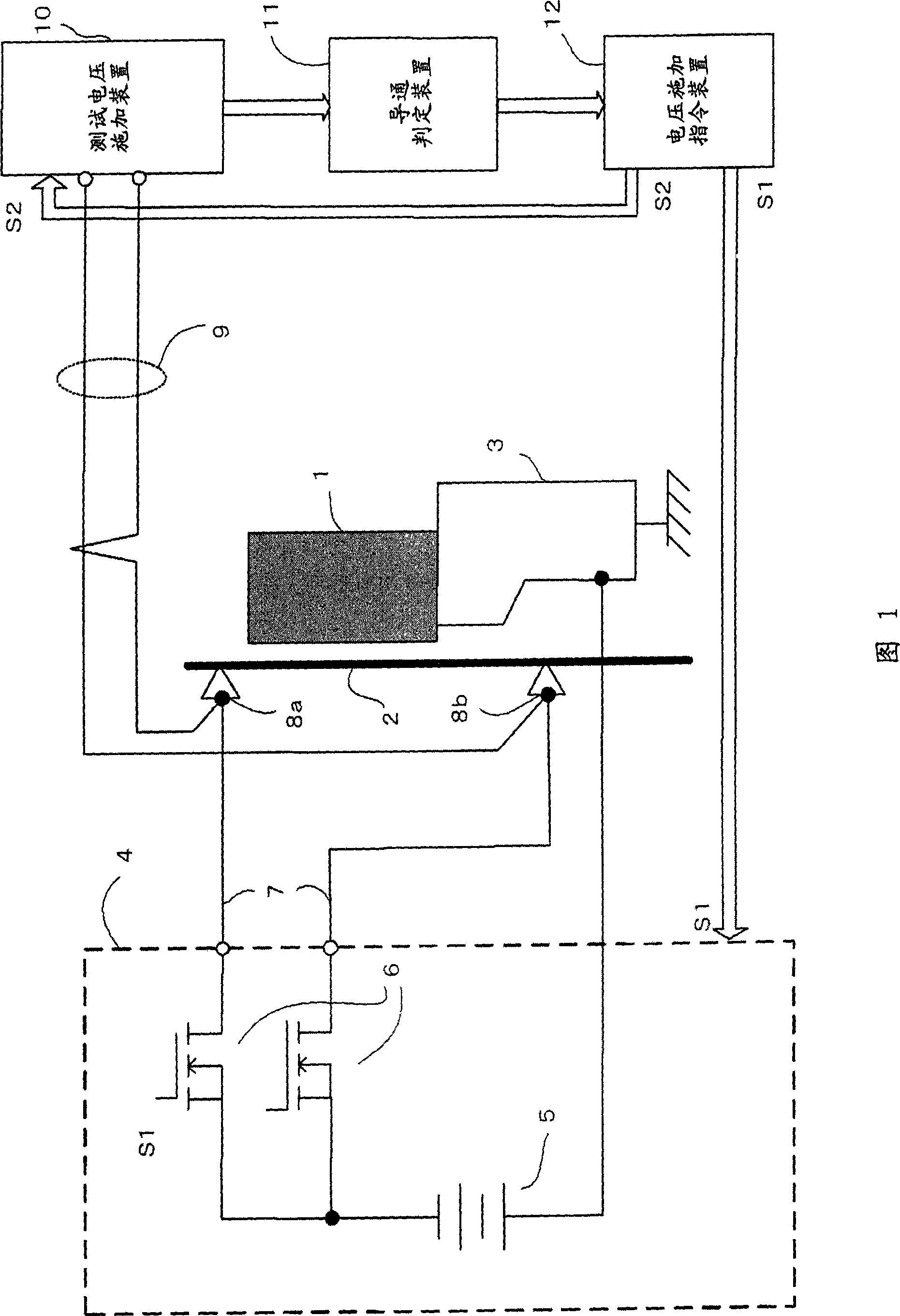
[0016] FIG. 1 is a schematic configuration diagram of an embodiment of a wire electrode disconnection detection device of the present invention.

[0017] The machining power source 4 includes a machining DC voltage source 5 and a switching element 6 for converting the DC voltage from the machining DC voltage source 5 to a pulse voltage and applying it to the wire electrode. In the machining DC voltage source 5 , one electrode is connected to the upper conductive mold 8 a and the lower conductive mold 8 b via the switching element 6 and the power supply line 7 , and the other electrode is connected to the workpiece placement table 6 .

[0018] In the switching element 6 , an application command signal S1 is input from the voltage application command device 12 . The switching element 6 converts the DC voltage from the machining DC voltage source 5 in accordance with the application command signal S1 into a cycle of the voltage application time and the rest time during electrical...


PUM


Abstract

In electric discharge machining for intermittently applying voltage pulses between a wire electrode and a workpiece with quiescent periods interposed, test voltage for checking conduction between upper and lower power feeding elements is applied during quiescent periods. When there is no conduction, it is determined that the wire electrode is broken between the upper and lower power feeding elements.

Description

technical field [0001] The present invention relates to a wire electrode disconnection detection device of a wire electric discharge machine, which detects the disconnection of a wire electrode of a wire electric discharge machine. Background technique [0002] The wire electric discharge machine generates intermittent discharge between the wire electrode and the workpiece (between electrodes), and moves the wire electrode and the workpiece relatively according to the state between the electrodes, thereby removing and machining the workpiece. In order to generate the intermittent discharge, a series of operations of applying a DC current between electrodes and then inserting a rest time are repeated. [0003] The machining conditions are set at the time of machining, but if the setting is not appropriate, machining becomes unstable, and the wire electrode may break suddenly. Then, when a DC power source from a machining power source is applied to the wire electrode immediat...

Claims


Application Information

Patent Timeline
Patent Type & Authority Applications(China)
IPC IPC(8): B23H7/02B23H7/14G01R31/02
CPCB23H7/02B23H7/04B23H7/102
Inventor 川原章义中岛廉夫
Owner FANUC LTD
Why Eureka
Try Eureka