Supercharge Your Innovation With Domain-Expert AI Agents!

Air cooling steam turbine steam discharge apparatus built-in with deoxidization apparatus

A steam turbine and steam exhaust technology, which is applied in the direction of mechanical equipment, engine components, machines/engines, etc., can solve the problem of inappropriate location arrangement of oxygen removal device, complex structure and system of oxygen removal device, uneven contact between steam and water mist, etc. problems, to achieve the effect of small disturbance, simple structure and rapid heat transfer

Active Publication Date: 2009-05-20
DONGFANG TURBINE CO LTD
View PDF3 Cites 9 Cited by
  • Summary
  • Abstract
  • Description
  • Claims
  • Application Information

AI Technical Summary

Problems solved by technology

[0004] 1. The structure of the oxygen removal device and its position in the exhaust device are not very appropriate, resulting in large steam resistance and poor circulation of the oxygen removal device. In order to ensure its flow area, an air extraction pipe has to be installed at the end of the oxygen removal device And it is connected to the inlet of the air extraction equipment, which makes the structure and system of the oxygen removal device complicated
[0005] 2. The nozzles of deaeration devices (including condensate deaeration devices and replenishment water deaeration devices) adopt water mist nozzles, and the sprayed water is in the form of mist, which is a kind of turbulent flow, which disturbs the steam flow and makes the steam flow out. It becomes a turbulent flow, the contact between the steam and the water mist is uneven, only part of the water mist is heated to the saturation temperature, and the rest is less than the saturation temperature, so the oxygen removal effect is poor. At the same time, the turbulent flow also increases the steam exhaust resistance.
[0006] 3. There are fillings in the condensate deaeration device, which may pollute the condensate

Method used


Image

  • Air cooling steam turbine steam discharge apparatus built-in with deoxidization apparatus
  • Air cooling steam turbine steam discharge apparatus built-in with deoxidization apparatus
  • Air cooling steam turbine steam discharge apparatus built-in with deoxidization apparatus

Examples


Embodiment Construction

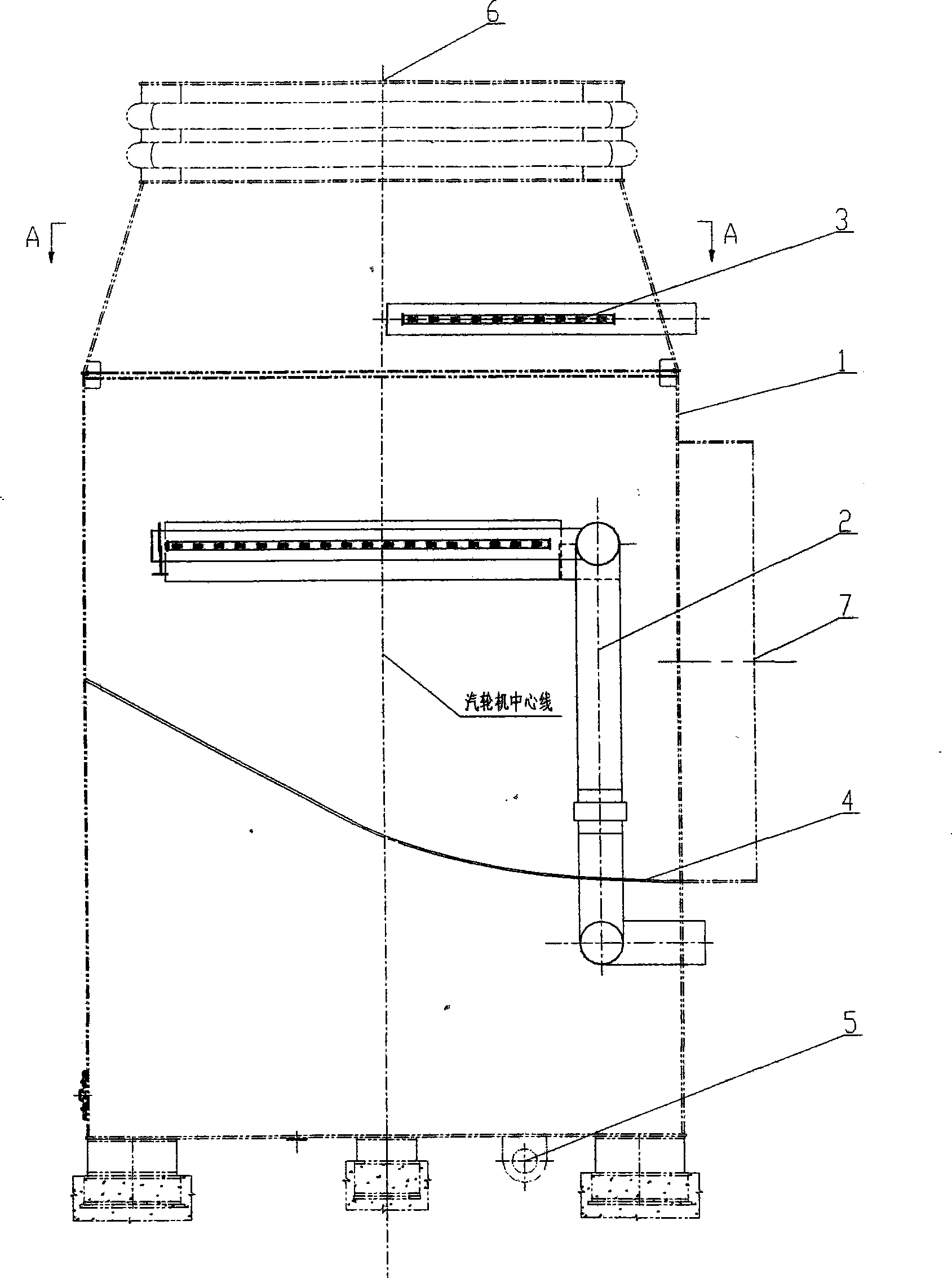
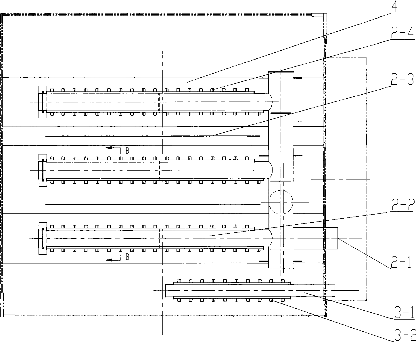
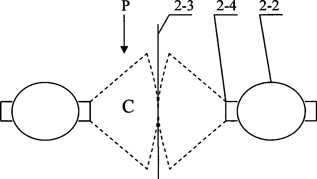
[0026] see Figure 1 to Figure 3 : This air-cooled steam turbine exhaust device with a built-in oxygen removal device includes an exhaust device 1, a condensed water deaeration device 2 and a water replenishment deaeration device 3 arranged in the exhaust device 1.

[0027] The steam exhaust device 1 is a box-shaped structure, the steam inlet 6 is set on the top wall of the box, the steam outlet 7 is set on the side wall of the box, and the lower part of the box has a water outlet 5; the box is equipped with a steam deflector 4 , located at the waist of the box and lower than the steam outlet 7, divides the inner space of the box into an upper chamber and a lower chamber, the upper chamber forms a steam channel, and the lower chamber forms a water collection tank. Condensed water deaeration device 2 and replenishment water deaeration device 3 are arranged in the upper chamber. There is a water passage on the deflector 4, and the heated and deoxidized water flows into the sump...


PUM


Abstract

The invention discloses an air cooling steam turbine vapor exhaust device with a built-in deaerating device. The air cooling steam turbine vapor exhaust device comprises a vapor exhaust device, and a condensation water deaerating device and a water supplementation deaerating device which are arranged inside the vapor exhaust device. The condensation water deaerating device has a tubular type structure and a plurality of water jet pipes arranged in parallel on the same plane. A plurality of nozzles arranged on the water jet pipes are distributed symmetrically in two rows and longitudinally along the water jet pipes. The jet direction of the nozzle is consistent with the arrangement direction of the water jet pipes. A splash board is arranged between two adjacent water jet pipes. The water supplementation deaerating device has a tubular structure; a plurality of nozzles arranged on the pipe are distributed symmetrically in the two rows and longitudinally along the pipe; the nozzles are film type nozzles; and the water film sprayed by the nozzles is in parallel with the flow direction of the vapor. The air cooling steam turbine vapor exhaust device has the advantages of simple structure and system, no operation needed during the running, condensation water pollution removal, good condensation water deaerating effect, and the like. The oxygen content in the condensation water can reach the national standard.

Description

technical field [0001] The invention relates to an air-cooled steam turbine, in particular to its exhaust steam deoxygenation device. Background technique [0002] The exhaust steam of the air-cooled steam turbine is naturally cooled by air. After the steam expands in the steam turbine and does work, it becomes exhausted steam. It enters the air-cooled condenser through the exhaust steam device, condenses into liquid water, and then pumps it into the boiler for recycling. Since there are inevitably leakage gaps in the steam passage of the steam turbine, the air enters the steam passage from these gaps, and the oxygen in the air will dissolve into the condensed water of the steam. In addition, there will always be loss of steam during the work process. Only relying on condensed water to return to the boiler for recycling, the water volume is not enough, and water needs to be replenished to maintain the water vapor balance of the circulation system. The replenishment water als...

Claims


Application Information

Patent Timeline
IPC IPC(8): F01D25/30B01D19/00
Inventor 许晔刘伟龙谭顺科徐梅徐成勇刘维信
Owner DONGFANG TURBINE CO LTD
Features
  • R&D
  • Intellectual Property
  • Life Sciences
  • Materials
  • Tech Scout
  • Unparalleled Data Quality
  • Higher Quality Content
  • 60% Fewer Hallucinations
Learn More