Double-stage injection type pre-film pneumatic atomizing nozzle

An atomizing nozzle and ejector technology, which is applied in the field of two-stage ejector pre-film pneumatic atomizing nozzles, can solve the problems of difficult application in industrial heating occasions, easy wear and tear of oil pumps, and poor fuel atomization quality. Improves fuel atomization and combustion performance, eliminates fuel pumps, and reduces air pressure

Inactive Publication Date: 2011-01-12
PEKING UNIV
View PDF0 Cites 0 Cited by
  • Summary
  • Abstract
  • Description
  • Claims
  • Application Information

AI Technical Summary

Problems solved by technology

When the centrifugal nozzle with small flow is burning heavy residual oil or even waste oil, nozzle clogging and coking, smoke and NO X The emission problem will be prominent, and the oil pump is prone to wear and function decline, making it difficult for practical application
Compared with centrifugal nozzles, pneumatic nozzles can reduce smoke, reduce coking, and lower NO X Emission, but not suitable for control, high air pressure conditions, complicated operation, not easy to apply to industrial heating occasions with small flow burners (machines)
The main disadvantage of the self-priming swirling pneumatic atomizing nozzle is the small fuel flow rate, the poor atomization quality of the fuel at the center, and the high fuel concentration, which may easily cause incomplete combustion and smoke.

Method used


Image

  • Double-stage injection type pre-film pneumatic atomizing nozzle
  • Double-stage injection type pre-film pneumatic atomizing nozzle
  • Double-stage injection type pre-film pneumatic atomizing nozzle

Examples


Embodiment Construction

[0050] Embodiments of the present invention will be described in detail below in conjunction with the accompanying drawings.

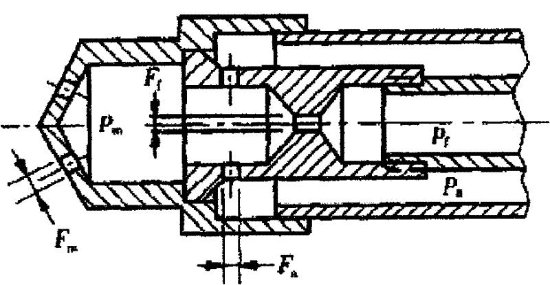
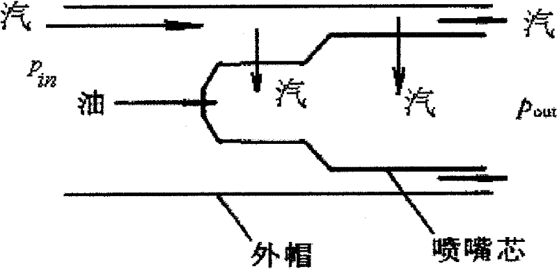
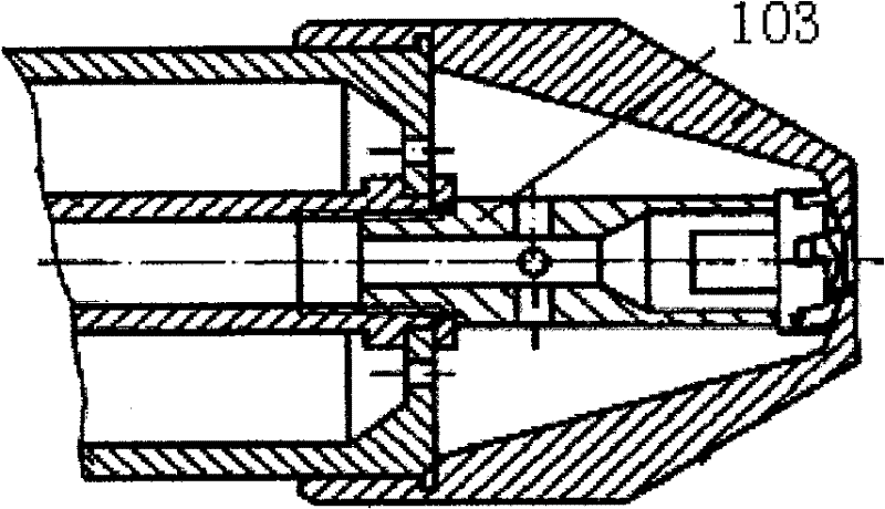
[0051] attached Figure 12 It is a schematic diagram of a two-stage injection pre-film pneumatic atomizing nozzle, which consists of a compression nut 1, an atomizing sheet 2, a guide sheet 3, a fixing piece 4, an oil and gas distributor 5, a central tube 6, and an air chamber seat 7 , air inlet 8, outer air inlet 9, inner air inlet 10, oil inlet 11, oil groove 12, tangential groove 13, swirl chamber 14, outer air ring port 15, oil ring outlet 16, inner air outlet Hole 17, spout 18 forms.

[0052] The compression nut 1 and the fixing part 4 are connected with the oil-gas distributor 5 through threads, and the atomizing sheet 2 and the deflector 3 are compressed through the compression nut 1 and the fixing part 4; the outlet of the atomizing sheet 2 is pressed against the compression nut 1 Tight, the inlet is pressed against the deflector 3; the upstr...


PUM


Abstract

The invention discloses a two-stage injection type pre-filming energy atomizing nozzle, relates to a fuel oil nozzle for a burner (combustor), and belongs to the field of industrial combustion. A compression nut, a fixing member, a central pipe and an air chamber seat are connected with an oil-gas distributor; an atomizing sheet and a guide vane are compressed through the compression nut and the fixing member; the atomizing sheet is an inner cone, and is provided with a tangential groove; the inside of the atomizing sheet is provided with the guide vane and an outlet of the central pipe in turn, and the atomizing sheet and the guide vane forms an external air annular opening; an oil ring outlet is formed between the guide vane and the central pipe; the atomizing sheet and the guide vane forms an outer gaseous port; the oil-gas distributor is provided with an external air inlet hole, an oil inlet hole and an oil groove; and the air chamber seat is provided with air inlet holes. Compared with a self-sucking cyclone pneumatic atomizing nozzle, the two-stage injection type pre-filming energy atomizing nozzle increases flow of fuel oil, improves atomizing quality of the fuel oil and rationality of oil-gas space distribution, improves combustion performance, reduces discharge of pollutant, does not coke and block, needs no oil pump, and is an ideal nozzle for a medium-low capacity burner (combustor) to combust heavy residual oil and waste oil.

Description

technical field [0001] The invention relates to a double-stage injection type pre-film pneumatic atomizing nozzle, which belongs to the fuel nozzle used in industrial combustion devices. Inhaled into the nozzle, the fuel forms an oil film on the wall, which is sheared and atomized by the internal and external high-speed airflow. The fuel atomization quality is high and the oil and gas space distribution is reasonable. The invention belongs to the field of energy power and industrial combustion. Background technique [0002] In industrial fuel combustion devices, nozzles are involved in atomizing liquid fuel into fine oil droplets, increasing the surface area of ​​the fuel, and having a reasonable spatial distribution of oil and gas to achieve high efficiency and low emissions, and the key is the mist of the fuel atomizing nozzle. performance. Therefore, the nozzle is a key component that affects the combustion performance of the fuel burner. Its quality directly affects th...

Claims


Application Information

Patent Timeline
Patent Type & Authority Patents(China)
IPC IPC(8): F23D11/38
Inventor 郑殿峰
Owner PEKING UNIV
Why Eureka
Try Eureka