
Self-absorption rotational flow pneumatic atomization nozzle device

A pneumatic atomization and nozzle device technology, which is applied in combustion methods, lighting and heating equipment, continuous combustion chambers, etc., can solve the problems that the atomization fineness is greatly affected by hydraulic pressure, small flow nozzles are blocked by carbon deposits, and oil pumps are prone to wear and tear. and other problems, to achieve the effects of good fuel atomization quality, enhanced combustion, good ignition and combustion performance

Inactive Publication Date: 2009-04-01
PEKING UNIV +1
View PDF0 Cites 27 Cited by
  • Summary
  • Abstract
  • Description
  • Claims
  • Application Information

AI Technical Summary

Problems solved by technology

Disadvantages: high processing precision requirements, small flow nozzles are prone to carbon deposition and clogging; atomization fineness is greatly affected by hydraulic pressure, requiring high oil pressure to work
When the centrifugal nozzle with small flow is burning heavy residual oil or even waste oil, nozzle clogging and coking, smoke and NO X Discharge problems will be prominent, while the oil pump is prone to wear and function degradation
Compared with centrifugal nozzles, pneumatic nozzles can reduce smoke, reduce coking, and lower NO X Emission, but need oil pump to provide pressure, not suitable for control, high air pressure conditions, complex operation

Method used


Image

  • Self-absorption rotational flow pneumatic atomization nozzle device
  • Self-absorption rotational flow pneumatic atomization nozzle device
  • Self-absorption rotational flow pneumatic atomization nozzle device

Examples


Embodiment 1

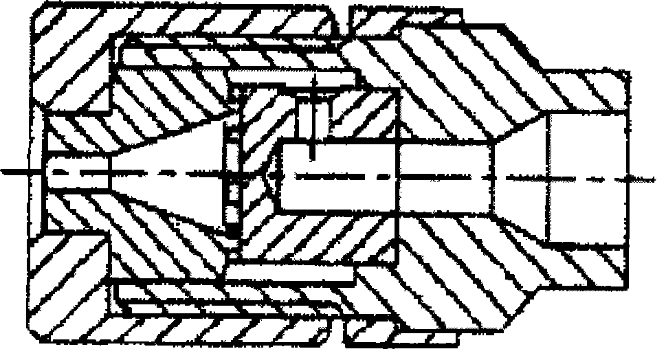
[0045] Embodiment 1: attached Figure 11 It is a schematic diagram of a self-priming swirling pneumatic atomizing nozzle device, which consists of a compression nut 1, an atomizing sheet 2, a swirling sheet 3, a guide sheet 4, a fixing piece 5, a sealing ring 6, a connecting piece 7, and an oil inlet hole 8. Air intake hole 9, air intake groove 10, tangential air hole 11, oil hole 12, swirl chamber 13, spray hole 14.

[0046] The compression nut 1 is connected with the connecting piece 7 and the fixing piece 5 through threads, and the atomizing piece 2, the swirl piece 3, and the guide piece 4 are compressed through the fixing piece 5; the outlet of the atomizing piece 2 is connected with the compression nut 1, The inlet is compressed with the swirl vane 3; the inlet of the swirl vane 3 is pressed with the guide vane 4, or the swirl vane 3 and the guide vane 4 are integrated, the middle is an oil hole, the outer side is an inclined groove, and the outlet is connected to the mi...

Embodiment 2

[0052] Self-priming swirl pneumatic atomizing nozzle device, including compression nut 1, atomizing sheet 2, swirl sheet 3, guide sheet 4, fixing piece 5, sealing ring 6, connecting piece 7, oil inlet hole 8, inlet Air hole 9, air inlet groove 10, tangential air hole 11, oil hole 12, swirl chamber 13, spray hole 14 are formed.

[0053] The compression nut 1 refers to a compression piece processed from copper, which is connected to the connecting piece 7 and the fixing piece 5 through threads, and the atomizing piece 2, the swirl piece 3, and the guide piece 4 are connected by the fixing piece 5 Compress to ensure that their centers are on the same axis; the atomizing sheet 2 refers to an inner cone processed with wear-resistant stainless steel, the rotating air flow accelerates the rotation at its inner edge, the outlet is compressed with the compression nut 1, and the inlet Compressed with the swirl sheet 3; the swirl sheet 3 refers to a cylindrical body processed by wear-res...


PUM


Abstract

The invention discloses a self-sucking swirl pneumatic atomizing nozzle device relating to a fuel atomizing evaporation mixing nozzle used for a full-automatic combustion engine and belongs to the field of industrial combustion systems. An atomizing sheet 2, a swirl sheet 3 and a stream guidance sheet 4 are compressed closely by a compression nut 1 and a fixing piece 5; the atomizing sheet 2 is an internal cone and the outlet of the atomizing sheet 2 is a spout 14; the swirl sheet 3 is provided with a tangential air hole 11; the outlet hole of the stream guidance sheet 4 is an oil hole 12 and the outlet of the stream guidance sheet 4 is a swirl chamber; the compression nut 1 is connected with the fixing piece 5 and a connecting piece 7; the outer surface of the upstream of the fixing piece 5 is provided with a seal ring 6; an oil inlet hole 8 is the inner hole of the connecting piece 7; an air inlet hole 9 is the connection hole of the connecting piece 7 along the radical and coaxial direction; compared with the existing centrifugal nozzle or pneumatic atomizing nozzle, the self-sucking swirl pneumatic atomizing nozzle device does not need an oil pump; has the advantages of improving the fuel atomizing evaporation mixing characteristic and the distribution uniformity of oil-gas space, improving the combustion performance, reducing contamination discharge, having no coking and plugging, and is an ideal nozzle for combusting the heavy oil and waste oil by the full-automatic combustion engine.

Description

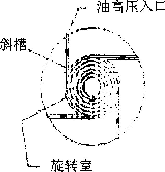
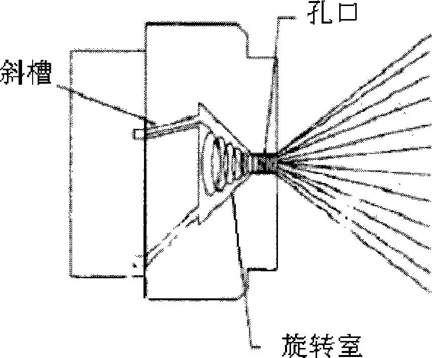
technical field [0001] The invention relates to a self-priming swirling pneumatic atomizing nozzle device, which belongs to the fuel nozzle used for a fully automatic burner. The negative pressure core area is generated by the swirling air flow in the nozzle, and the fuel in the fuel tank is sucked into the nozzle by the oil pipe, and after rotating Due to the aerodynamic force of the airflow, the fuel begins to atomize and is sent out of the nozzle along with the airflow, thereby generating an oil mist field with a certain spatial distribution. The invention belongs to the field of industrial combustion systems. Background technique [0002] In industrial fuel combustion devices, it involves atomizing liquid fuel into fine oil droplets, and has a reasonable spatial distribution of oil and gas to maximize combustion efficiency and reduce harmful gas emissions. The key is the mist of the fuel atomization nozzle. performance. The basic principle of the nozzle is to make the ...

Claims


Application Information

Patent Timeline
Patent Type & Authority Applications(China)
IPC IPC(8): F23R3/38
Inventor 郑殿峰张海洪
Owner PEKING UNIV
Learn More