Developing device and image forming device
A developing device and developer technology, which are applied in the direction of electric recording process applying charge pattern, equipment for applying electric recording process of charge pattern, electric recording technique, etc., can solve the problems of wear and deterioration with time change, etc. , the effect of reduced retention, reduced retention
- Summary
- Abstract
- Description
- Claims
- Application Information
AI Technical Summary
Problems solved by technology
Method used
Image
Examples
Embodiment 1
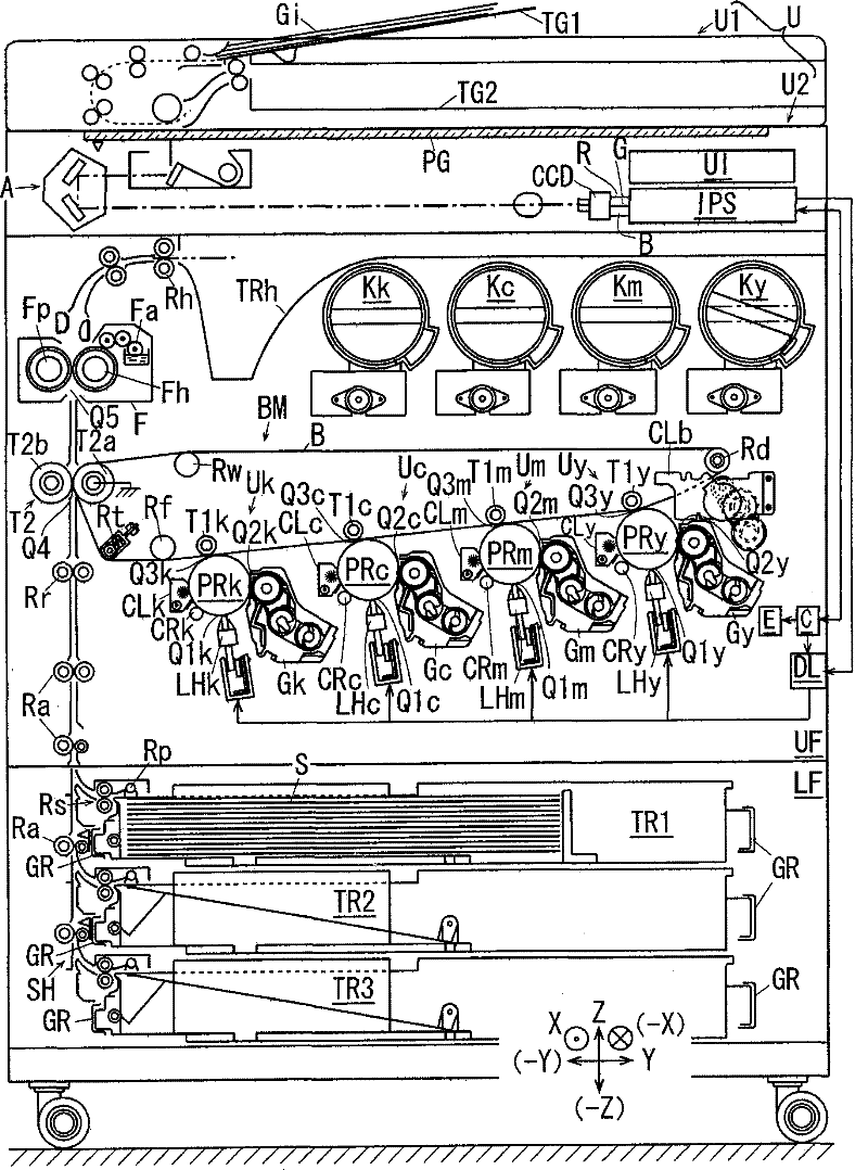
[0072] figure 1 It is an overall explanatory view of the image forming apparatus according to Embodiment 1 of the present invention.
[0073] exist figure 1 Among them, the image forming apparatus U has: an automatic document feeder U1; and an image forming apparatus main body U2 supporting the automatic document feeder U1 and having a transparent document reading surface PG at the upper end.
[0074] The automatic document feeder U1 has: a document feeder TG1 that stacks and stores a plurality of documents Gi to be copied; The document Gi conveyed by the upper document reading position.
[0075] The image forming apparatus main body U2 includes: an operation unit UI for allowing a user to input operation command signals such as operation start of an image forming operation; and an exposure optical system A and the like.
[0076] The reflected light from the document conveyed above the document reading surface PG by the automatic document conveying device U1 or the document...
Embodiment 2
[0136] Next, Embodiment 2 of the present invention will be described. In the description of Embodiment 2, constituent elements corresponding to those of Embodiment 1 will be assigned the same reference numerals, and detailed description thereof will be omitted.
[0137] The second embodiment differs from the first embodiment in the following points, and has the same configuration as the first embodiment in other respects.
[0138] Figure 7 It is an enlarged view of main parts of the crushing unit of Example 2.
[0139] Figure 8 It is a cross-sectional view of the main part of the third inflow part of embodiment 2, which is the same as that of embodiment 1. Figure 5 corresponding figure.
[0140] exist Figure 7 , Figure 8In the developing devices Gy to Gk of Embodiment 2, the crushing and conveying member 41 and the eccentric cam portion 28f of Embodiment 1 are omitted, and as an example of the crushing member, a so-called spring spiral formed by forming a wire rod in...
Embodiment 3
[0148] Next, Embodiment 3 of the present invention will be described. In the description of this Embodiment 3, the constituent elements corresponding to those of Embodiments 1 and 2 are assigned the same reference numerals, and detailed description thereof will be omitted.
[0149] This third embodiment differs from the aforementioned embodiments 1 and 2 in the following points, and is configured in the same manner as the aforementioned embodiments 1 and 2 in other respects.
[0150] Fig. 9 is an explanatory diagram of a pulverizing member of Example 3, Figure 9A is the floor plan, Figure 9B It is a sectional view of the main part.
[0151] In FIG. 9 , in the developing devices Gy to Gk of Embodiment 3, as an example of a crushing member, a so-called spring coil crushing coil 61 formed by forming a wire rod in a helical shape is disposed at the replenishment inflow portion E3 . The rear end 61 a of the crushing coil 61 is fixedly supported by the partition wall 12 , and th...
PUM
 Abstract
Description
Claims
Application Information
 - R&D
- Intellectual Property
- Life Sciences
- Materials
- Tech Scout
- Unparalleled Data Quality
- Higher Quality Content
- 60% Fewer Hallucinations
Browse by: Latest US Patents, China's latest patents, Technical Efficacy Thesaurus, Application Domain, Technology Topic, Popular Technical Reports.
© 2025 PatSnap. All rights reserved.Legal|Privacy policy|Modern Slavery Act Transparency Statement|Sitemap|About US| Contact US: help@patsnap.com


