
Light packet switching structure based on light code division multiplexing

A technology of optical packet switching and division multiplexing, which is applied in the direction of wavelength division multiplexing system, selection device of multiplexing system, coupling of optical waveguide, etc. Limited optical network bandwidth and other issues

Inactive Publication Date: 2009-05-20
UNIV OF ELECTRONICS SCI & TECH OF CHINA
View PDF0 Cites 19 Cited by
  • Summary
  • Abstract
  • Description
  • Claims
  • Application Information

AI Technical Summary

Problems solved by technology

[0002] In the optical network, the switching nodes that implement the switching function after photoelectric conversion are increasingly unable to handle the rapidly increasing transmission services, and an electronic bottleneck that limits the bandwidth of the optical network appears.

Method used


Image

  • Light packet switching structure based on light code division multiplexing
  • Light packet switching structure based on light code division multiplexing
  • Light packet switching structure based on light code division multiplexing

Examples


Embodiment Construction

[0019] In order to facilitate problem description, preferred specific implementations of the present invention will be described below in conjunction with the accompanying drawings. However, it should be noted that, in order to avoid diluting the subject matter of the present invention, known technologies and functions adopted in the system will be simplified or omitted in the corresponding description.

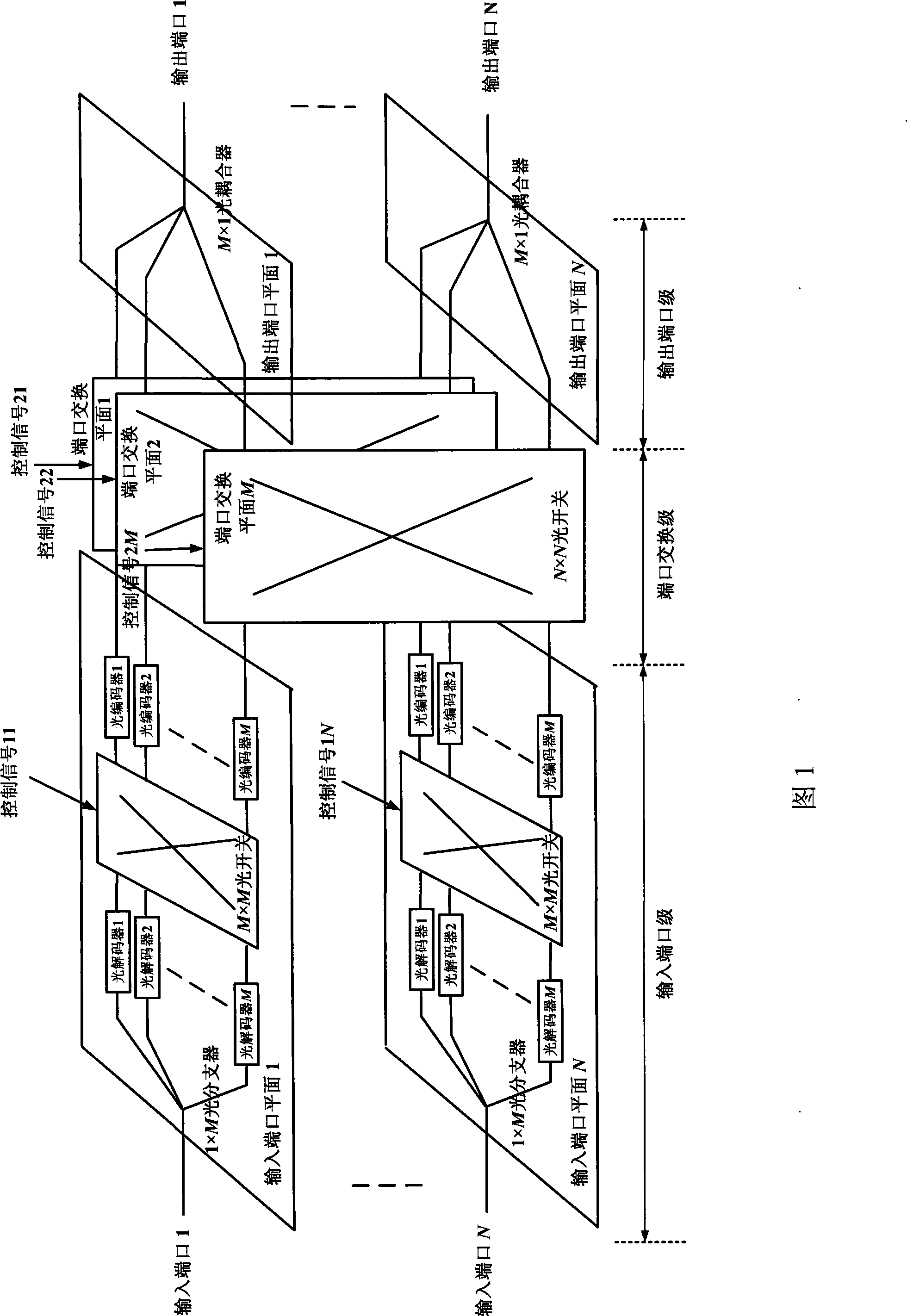
[0020] FIG. 1 is a structural diagram of a specific embodiment of optical packet switching based on optical code division multiplexing in the present invention. In this embodiment, in the optical packet switching structure based on optical code division multiplexing of the present invention, N input port planes form the input port level, M port switching planes form the port switching level, and N output port planes form the output port level .

[0021] In this embodiment, each input port 1-N of the optical packet switching structure based on optical code division multiplexi...


PUM


Abstract

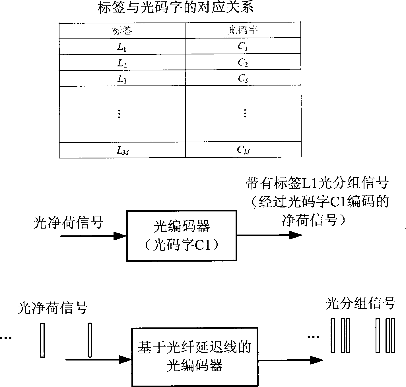
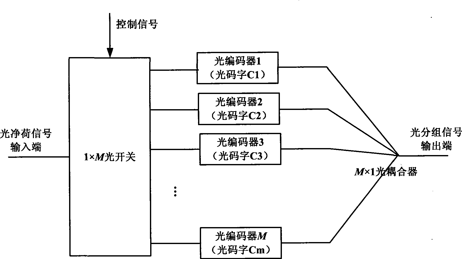
The invention discloses an optical packet switching structure on the basis of optical code division multiplexing, which adopts two stages of optical switches to perform interconnection, wherein the first stage optical switch, namely the optical switch in an input port plane, is connected with optical decoders and optical coders to achieve label update; and the second stage optical switch, namely the optical switch in a port exchange plane, is connected with different input / output ports to achieve port exchanges. According to the corresponding relation between an input label and an output label in certain input port in a label forwarding table, the connection relation between each optical coder and each optical decoder is determined, and the connection relation is achieved through driving the optical switch in the input port plane by a control signal. The connection relation between the output ports of the optical coder is determined according to the input port in the label forwarding table and the output port corresponding to the input label, and the connection relation is achieved through driving the optical switch in the port exchange plane by the control signal. Therefore, the optical packet label update and the port exchange are achieved.

Description

technical field [0001] The invention belongs to the technical field of optical fiber communication, and specifically relates to an optical packet switching structure based on optical code division multiplexing. technical background [0002] In the optical network, the switching nodes that implement the switching function after photoelectric conversion are increasingly unable to handle the rapidly increasing transmission services, and an electronic bottleneck that limits the bandwidth of the optical network appears. [0003] Optical packet switching technology uses optical switching instead of electrical switching, which overcomes the signal integrity problem of high-speed electrical signals during transmission, and avoids the increase in signal rising and falling edges caused by the response of electronic devices during storage and processing. And other problems, can realize the processing optical signal of wire speed. At the same time, the optical packet switching technolo...

Claims


Application Information

Patent Timeline
IPC IPC(8): H04Q11/00H04J14/02G02B6/26
Inventor 凌云邱昆
Owner UNIV OF ELECTRONICS SCI & TECH OF CHINA
Learn More