Cooling system for a fuel cell

A cooling system, fuel cell technology, applied in fuel cells, fuel cell additives, circuits, etc., can solve problems such as reducing the efficiency of fuel cell systems

Active Publication Date: 2009-05-20
FRONIUS INTERNATIONAL GMBH
View PDF4 Cites 4 Cited by
  • Summary
  • Abstract
  • Description
  • Claims
  • Application Information

AI Technical Summary

Problems solved by technology

Here, additional components are also required for deioniza

Method used


Image

  • Cooling system for a fuel cell
  • Cooling system for a fuel cell
  • Cooling system for a fuel cell

Examples


Embodiment Construction

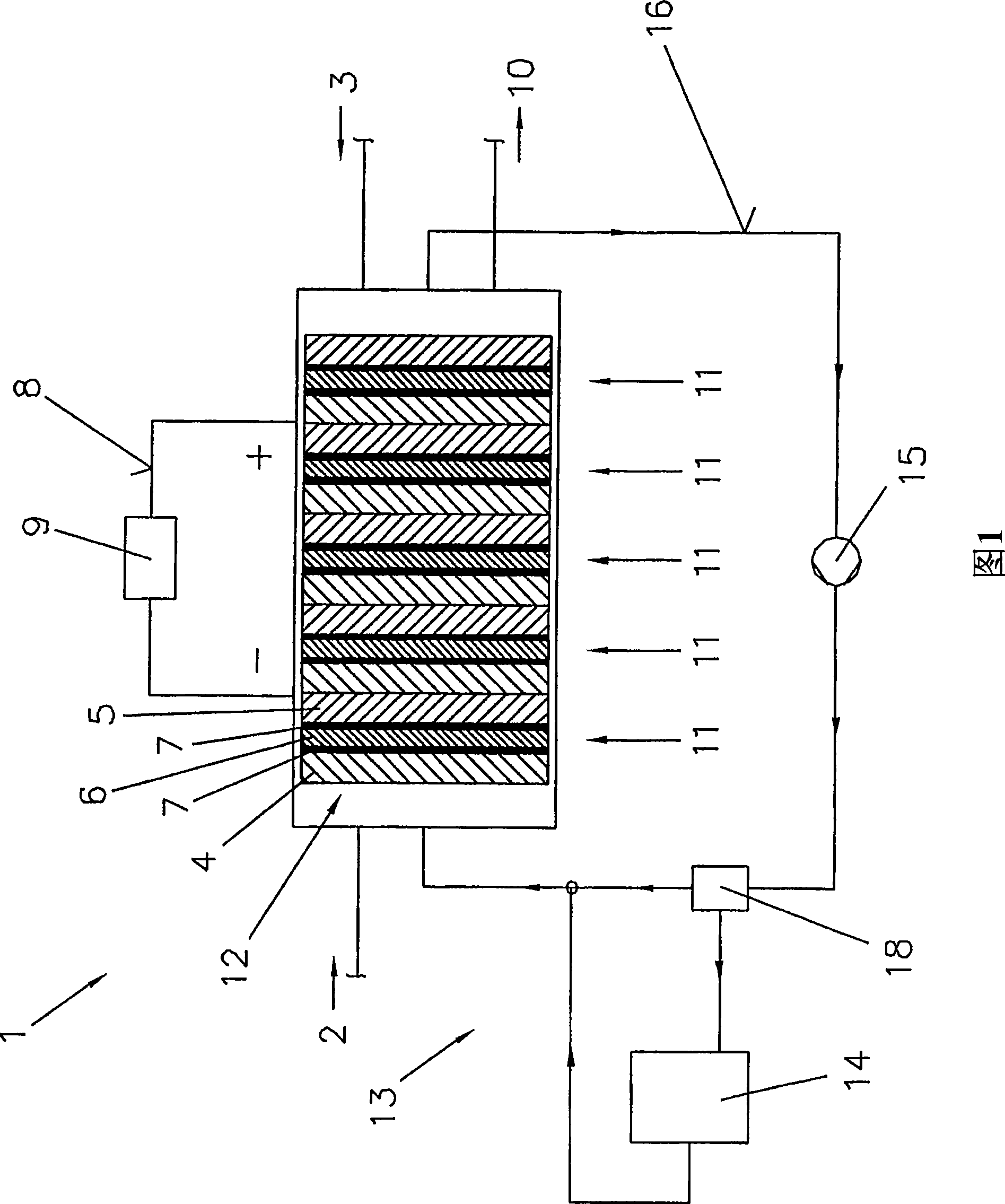
[0032] At the outset, like reference numerals have been assigned to like parts of the illustrated embodiment.

[0033] In FIG. 1 , a fuel cell 1 is shown for generating electrical current from hydrogen 2 and oxygen 3 or air, respectively.

[0034] In general, the fuel cell 1 is an electrochemical current generator that generates electrical current directly from chemical reactions. This is achieved by splitting water by inverse electrolysis, in which the gases hydrogen2 and oxygen3 are formed by the flow of electric current.

[0035] This means that in the fuel cell 1, hydrogen 2 reacts with oxygen 3, thereby generating an electric current. For this, hydrogen 2 is supplied to the anode 4 and oxygen 3 to the cathode 5 , which are separated by an electrolyte 6 . Furthermore, the anode 4 and the cathode 5 are coated on their sides facing the electrolytic solution 6 with a catalyst 7 mainly formed of platinum. In this way, hydrogen 2 can react with oxygen 3 , which takes place i...


PUM


Abstract

The invention relates to a cooling system (13) for a fuel cell (1) having at least one cooler (14), a thermostat (18), a pump (15) for delivering a coolant (17) in a cooling cycle (16), and having an equalization container (20), wherein a deionizing resin (19), which is arranged in the equalization container (20), is provided for reducing the electrical conductivity of the coolant (17), and wherein the equalization container (20) is connected to the cooling cycle (16) via at least one line (21). In order to provide such a cooling system (13), in which the electrical conductivity of the coolant (17) can be kept continuously low in a simple and cost-effective manner, provision is made for the deionizing resin (19) to be arranged in a container (22) in an interior (24) of the equalization container (20) such that the deionizing resin (19) enters at least partially into the coolant (17) and the line (21), which connects the equalization container (20) and the cooling cycle (16), is freely accessible.

Description

technical field [0001] The invention relates to a cooling system for a fuel cell comprising at least one cooler, a thermostat, a pump for delivering coolant in a cooling circuit, and an equalization container, wherein the deionized resin located in the equalization container is provided for In order to reduce the conductivity of the coolant, the equalization container is connected to the cooling circuit by at least one pipe. [0002] The invention also relates to a cooling system for a fuel cell comprising at least one cooler, a thermostat, a pump for delivering the coolant in the cooling circuit and an equalization container, in which a deionized resin is placed for reducing cooling conductivity of the agent. [0003] The invention relates to a cooling system for a fuel cell in which the conductivity of the coolant located in the cooling system is kept as low as possible (less than 50 μS / cm) in order to prevent secondary reactions in the cooling circuit of the fuel cell. B...

Claims


Application Information

Patent Timeline
IPC IPC(8): H01M8/04
CPCH01M8/04044Y02E60/50H01M8/04029
Inventor 马丁·布欣格尔亚历山大·贡西奥尔马蒂亚斯·格里斯鲍姆
Owner FRONIUS INTERNATIONAL GMBH
Why Eureka
Try Eureka