Engine electric generator unit

A technology for generator sets and engines, which is applied in the cooling of engine components, machines/engines, and engines, can solve the problems of difficult heat dissipation of mufflers, and achieve the effects of simple structure, convenient movement and sufficient cooling.

Active Publication Date: 2011-02-02
WUXI KIPOR POWER CO LTD
View PDF1 Cites 0 Cited by
  • Summary
  • Abstract
  • Description
  • Claims
  • Application Information

AI Technical Summary

Problems solved by technology

However, since the exhaust muffler is enclosed under the partition, it is even more difficult to dissipate heat from the muffler.

Method used


Image

  • Engine electric generator unit
  • Engine electric generator unit
  • Engine electric generator unit

Examples


Embodiment Construction

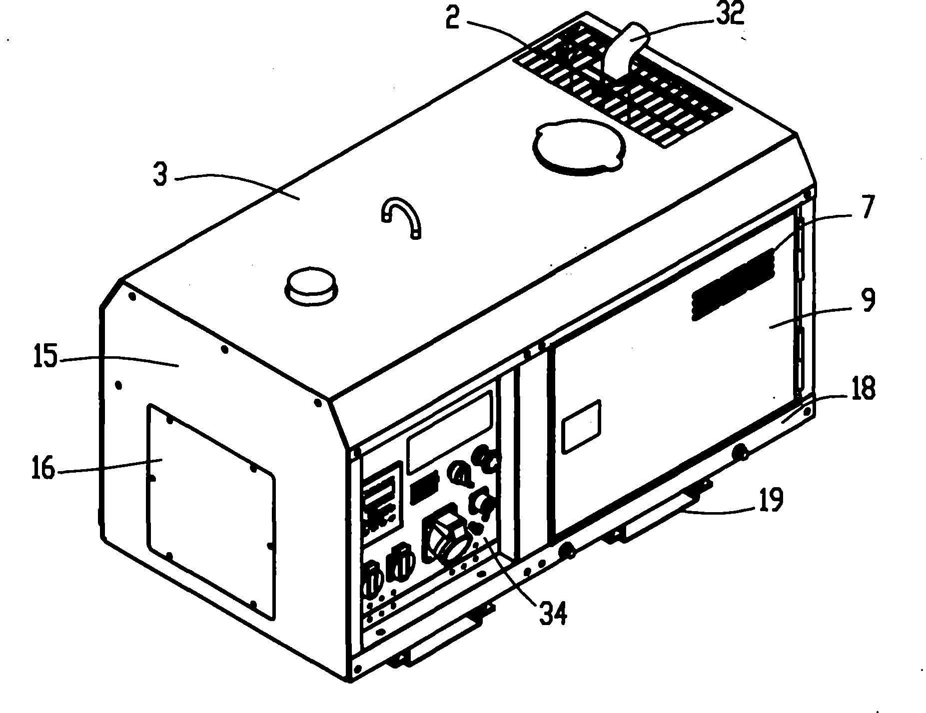
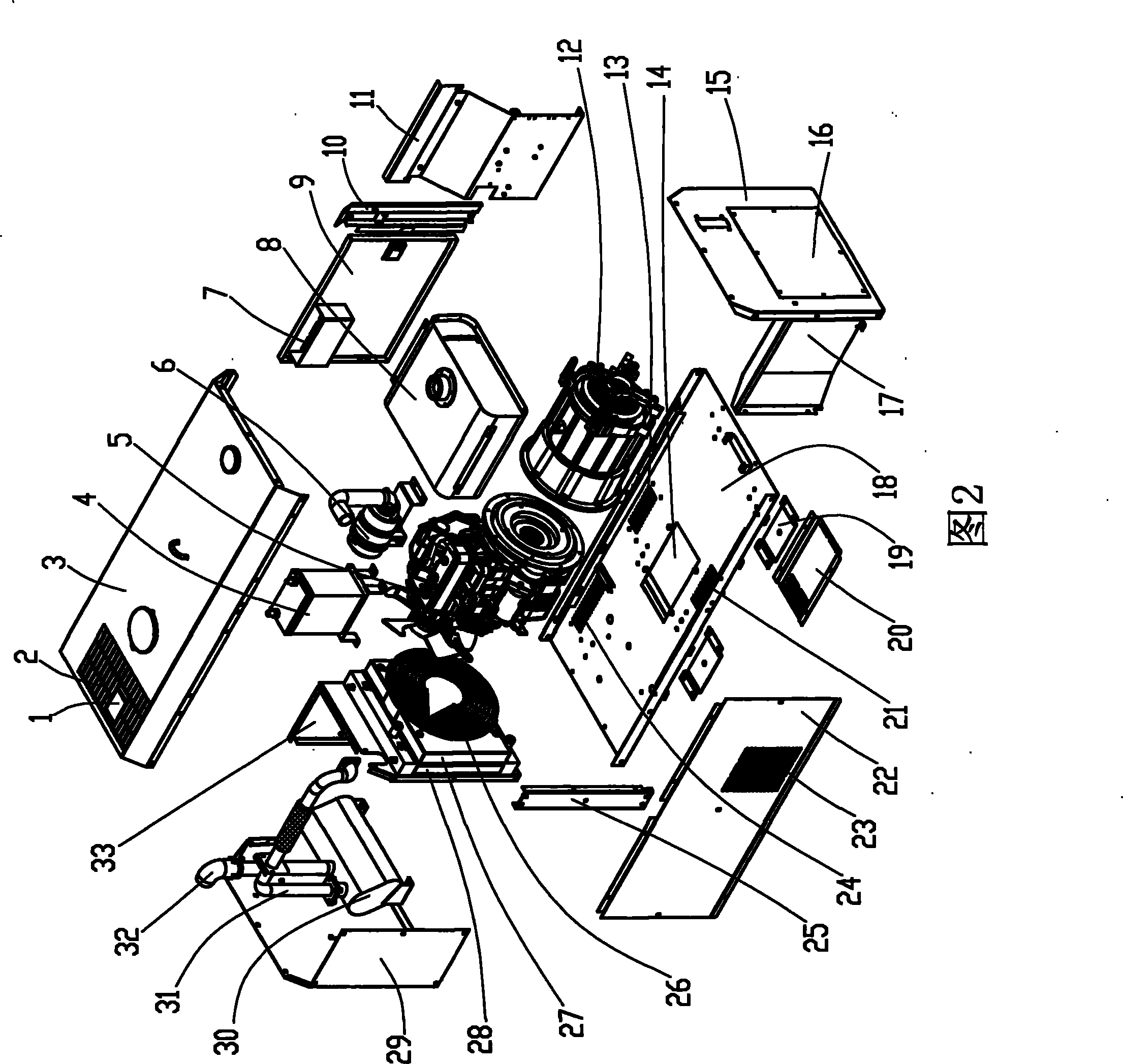
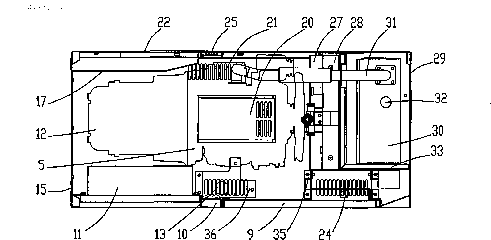
[0031] Below the present invention will be further described in conjunction with the embodiment in the accompanying drawing:

[0032] Figure 1 to Figure 14 As shown, it includes exhaust port 1, exhaust grille 2, top cover 3, battery 4, engine 5, air filter 6, door panel intake grille 7, fuel tank 8, door panel 9, front pillar 10, and rear panel Cover 11, generator 12, first air intake grille 13, air intake hole 14, right enclosure plate 15, right cover plate 16, air channel plate 17, chassis 18, backing plate 19, bottom plate air intake plate 20, second Air inlet grille 21, rear cover plate 22, rear cover air inlet grille 23, third air inlet grille 24, rear column 25, fan guard 26, water tank guard 27, radiator 28, left panel 29, Muffler 30, exhaust pipe 31, exhaust tail pipe 32, left partition 33, panel 34, battery support plate 35, air filter support plate 36, guard plate 37, support plate 38, bottom plate 39, rear reinforcement plate 40, rear Column mounting hole 41, bac...


PUM


Abstract

The invention relates to an electric generating set of an engine arranged in an enclosed cabinet, which comprises the cabinet. The engine, an electric generator coaxially connected with the engine, and a muffler, a radiator, a battery cell, an air cleaner and an oil tank connected with the engine are arranged in the cabinet; the oil tank is arranged above the electric generator; and the air cleaner is arranged in the front of the engine. The electric generating set is characterized in that a left partition board is arranged in the cabinet; the left partition board and the inner walls of the cabinet form a cavity; the muffler is arranged in the cavity; and the radiator is fixed on the left partition board and communicated with a cooling pipeline of the engine. Because the left partition board is arranged in the cabinet, the left partition board and the inner walls of the cabinet form the cavity, and the muffler is arranged in the cavity, the electric generating set has quite simple structure, and can effectively avoid influence of heat of the muffler on other components in the cabinet.

Description

technical field [0001] The invention relates to an engine generator set, in particular to an engine generator set in which an engine and a generator coaxially connected with the engine are installed in a closed cabinet. Background technique [0002] The engine generator set is generally composed of an engine and a generator coaxially installed in a closed cabinet. When the unit is working, it will generate a lot of heat. Only when the heat is discharged from the cabinet in time can the normal operation of the unit be guaranteed. For the unit with water-cooled engine, because the engine is forced water-cooled, the heat dissipation of the engine body is more timely and efficient, but the exhaust muffler of the generator and the engine is generally difficult to dissipate heat because it is air-cooled. Especially the muffler, which is a high-temperature component in the cabinet, if the heat of the muffler cannot be discharged from the cabinet in time, the temperature in the cab...

Claims


Application Information

Patent Timeline
Patent Type & Authority Patents(China)
IPC IPC(8): F02B63/04F02B77/11F01P1/06
CPCF02B63/04F01P2001/005F02B63/044
Inventor 肖亨琳
Owner WUXI KIPOR POWER CO LTD
Why Eureka
Try Eureka