Lubrication apparatus of horizontal rotary compressor and control method thereof

A technology of rotary compressors and lubricating devices, which is applied in the direction of rotary piston machinery, components of pumping devices for elastic fluids, rotary piston type/oscillating piston type pump components, etc., which can solve the problem of sacrificing cooling and reducing reliability , the motor is easy to burn out, etc., to achieve the effect of balanced cooling and reduced oil discharge

Active Publication Date: 2009-05-27
GUANGDONG MEIZHI COMPRESSOR
View PDF0 Cites 21 Cited by
  • Summary
  • Abstract
  • Description
  • Claims
  • Application Information

AI Technical Summary

Problems solved by technology

In conventional horizontal rotary compressors, as the working conditions change, the oil level inside the housing fluctuates greatly. As a result, the reliability decreases due to insufficient oil supplied to the compression components, and the am

Method used


Image

  • Lubrication apparatus of horizontal rotary compressor and control method thereof
  • Lubrication apparatus of horizontal rotary compressor and control method thereof
  • Lubrication apparatus of horizontal rotary compressor and control method thereof

Examples


no. 1 example

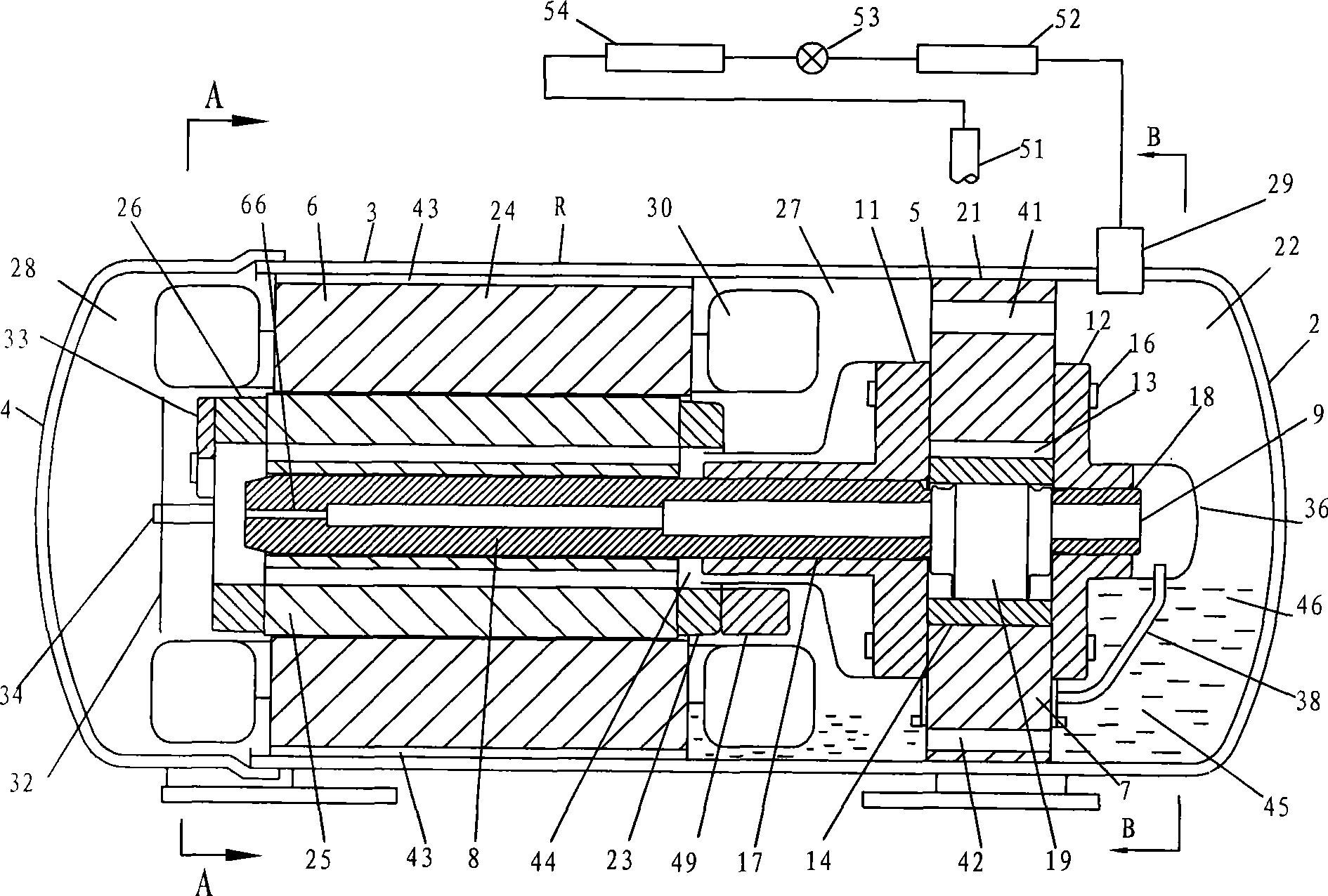
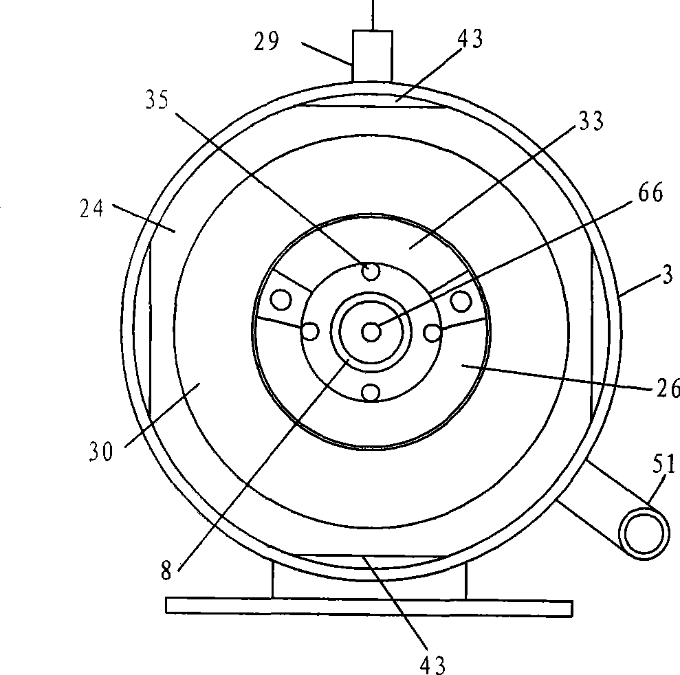
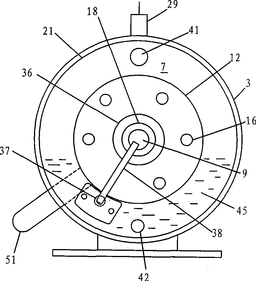
[0022] see Figure 1-Figure 4 , The airtight casing 2 of the horizontal rotary compressor R is composed of a main casing 3 and a side casing 4 , and the compressor assembly 5 and the motor 6 are fixed and accommodated in the inner cavity of the main casing 3 .

[0023] The compressor assembly 5 includes a cylinder 7, the main bearing 11 and the auxiliary bearing 12 are installed on the surface of both sides of the cylinder 7, and support the crankshaft 8, the circular piston 14 located in the center of the cylinder and accommodated in the cylinder compression chamber 13, and the piston 14 The outer periphery of the sliding plate is in relative sliding contact, and the sliding plate is not shown in the figure. Above each parts are combined by cylinder screw 16. The crankshaft 8 is composed of a main shaft 17 , a counter shaft 18 and an eccentric shaft 19 . The piston 14 is mounted on the eccentric shaft 19 and revolves in the cylinder compression chamber 13 . The cylinder out...

no. 2 example

[0038] see Figure 5-Figure 6 , with respect to the first embodiment, the second embodiment has the following three alternatives: enlarge the outer circumference of the main bearing 11, fix it on the inner diameter of the main housing 3, and also support the entire compressor assembly 5; and add Utilize the pressure-reducing means of the second end ring 26 of the rotor 25, that is, form a pressure difference through its high-speed rotation, so that the high-pressure gas of the exhaust muffler 39 can easily flow out to the second motor chamber 28; The connection method of one end ring 23.

[0039] The outer circumference of the main bearing 11 is almost equal to the inner diameter of the main casing 3, and the compressor assembly 5 is fixed on the outer circumference. An auxiliary plate 61 having an L-shaped inner diameter cylindrical portion is installed on the first end ring 23 , and the first balance weight 49 is installed on it. When the gap between the muffler exhaust ho...


PUM


Abstract

The invention discloses a lubrication device of a horizontal rotary compressor and a control method thereof. The lubrication device comprises a compression component and a motor which are fixed in a closed shell through the periphery thereof respectively; the shell and the motor are divided into an oil chamber, a first motor chamber and a second motor chamber through a cylinder and a main bearing or an auxiliary bearing; the compression component is provided with an exhaust silencer; a rotor is provided with an axially through rotor air hole; an outlet of the exhaust silencer is communicated with the first motor chamber; and one end of the rotor air hole is communicated with the first motor chamber, while the other end is communicated with the second motor chamber. The adoption of the technical proposal can ensure that oil diffused into the closed shell can be mostly recovered and stored in the oil chamber in any working condition of the compressor, thereby continuously supplying oil for the compression component. Moreover, when exhaust gas containing small amount of oil is moved from the second motor chamber to the first motor chamber, the oil can be separated out, so the bleeding oil amount is reduced, and a motor winding can be evenly cooled.

Description

technical field [0001] The invention relates to a horizontal rotary compressor, in particular to a lubricating device and a control method for a horizontal rotary compressor whose shell inner pressure is high pressure. Background technique [0002] In recent years, in the trend of popularizing rotary compressors all over the world, in order to reduce the system volume of air conditioners, refrigeration machines, etc., and to expand the effective volume of the system, the application of horizontal rotary compressors is increasing. In conventional horizontal rotary compressors, as the working conditions change, the oil level inside the housing fluctuates greatly. As a result, the reliability decreases due to insufficient oil supplied to the compression components, and the amount of oil discharged to the system increases. resulting in performance degradation. And in order to control the oil level, the cooling of the motor winding by the exhaust gas is sacrificed, causing the p...

Claims


Application Information

Patent Timeline
IPC IPC(8): F04C29/02F04C29/04F04C28/00F04C18/356
Inventor 小津政雄姜晋成梁自强
Owner GUANGDONG MEIZHI COMPRESSOR
Why Eureka
Try Eureka