Pressure exchanger

A technology of pressure exchanger and low pressure, which is applied in the direction of fluid pressure converter, machine/engine, mechanical equipment, etc. It can solve the problems of volumetric efficiency drop, large relative leakage rate, and difficult formation of pressure exchanger, so as to achieve the accuracy of convenient speed The effect of control, self-tightening seal with small leakage and high energy recovery efficiency

Active Publication Date: 2009-05-27
杭州帕尔水处理科技有限公司
View PDF2 Cites 21 Cited by
  • Summary
  • Abstract
  • Description
  • Claims
  • Application Information

AI Technical Summary

Problems solved by technology

[0006] This kind of rotary pressure exchanger is disclosed in Chinese patent 98809685.4. The pressure exchanger uses the tangential impulse of high pressure and low pressure water flow as the driving force of the rotor rotation. There must be a clearance fit between the rotor and the two end covers (98809685.4 specification No. 4/ Page 5: the sleeve is slightly longer than the rotor), and for this reason, a certain amount of water leaks from the high-pressure flow path to the low-pressure flow path on the distribution surface between the rotor and the two end covers (the rotor with a diameter of 100mm The leakage water flow rate is about 200L/h on the gap between the two end faces of about 5μm). In the case of a small water flow rate of the pressure exchanger, because the absolute leakage flow rate of high-pressure water remains unchanged, it is different from the high-pressure water flow rate. The ratio, that is, the relative leakage rate will be greatly increased, so that the volumetric efficiency will be greatly reduced, and the tangential impulse of the small flow of water flow cannot make the rotor rotate stably; in another...

Method used


Image

  • Pressure exchanger
  • Pressure exchanger
  • Pressure exchanger

Examples


Embodiment Construction

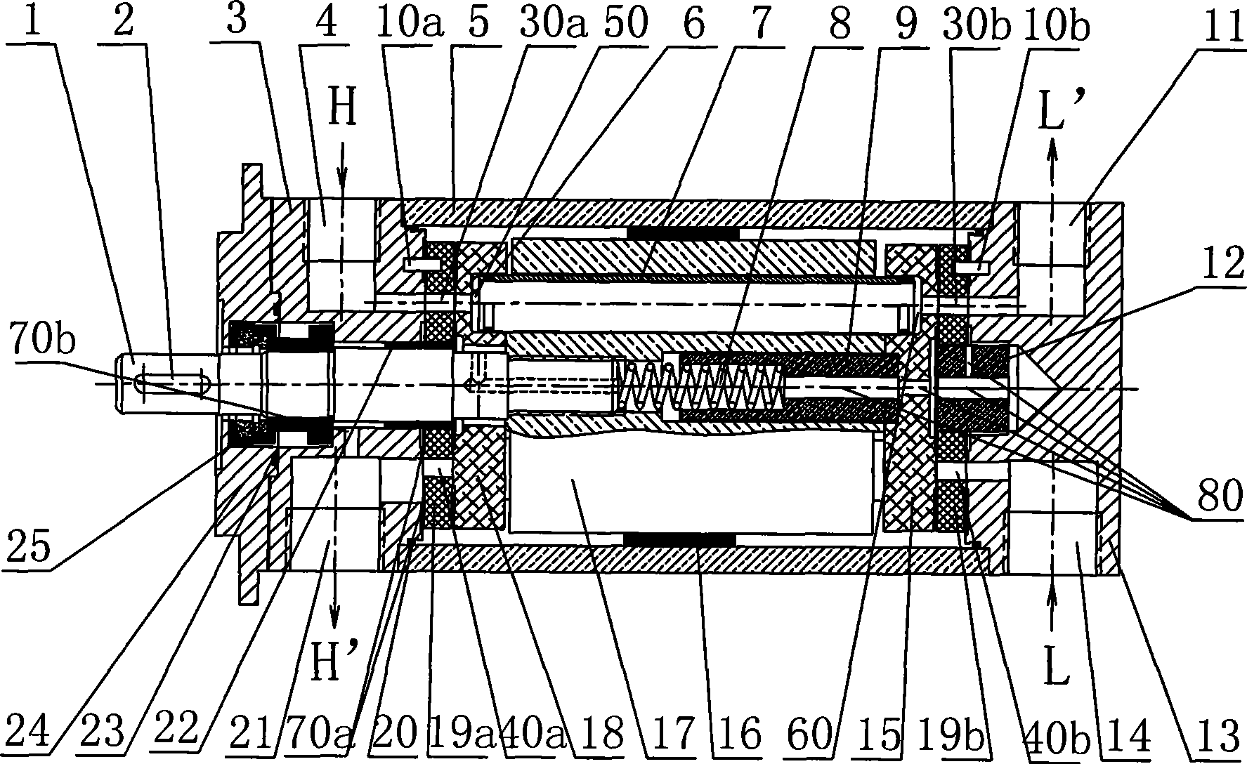
[0033] As shown in the figure, the present invention includes a rotating assembly, and the rotating assembly includes: a drive shaft 1, a rotor 17, a left thrust plate 18 and a right thrust plate 15 located on both sides of the rotor 17, a spring 8, and a spring 8. The pressing rod 9 of the right thrust plate 15 is squeezed to the right, and the right end of the pressing rod is arranged coaxially with the drive shaft and pressed against the right thrust plate 15. The spring is between the pressing rod and the drive shaft. The left thrust plate 18 and the right thrust plate 15 are slidable in the axial direction of the drive shaft and the distance between them is greater than the length of the rotor; several shafts with the drive shaft are evenly arranged in the rotor 17 along the circumference of the rotor To the parallel holes, the distribution pipes 7 are respectively arranged in the holes. In this embodiment, a total of 5 holes are provided, and accordingly, a total of 5 dis...


PUM


Abstract

The invention provides a pressure exchanger, which comprises a rotating component. The rotating component comprises a driving shaft, a rotor, a left thrust disk and a right thrust disk positioned on two sides of the rotor respectively, a spring, and a compaction bar acted by the spring to thrust the right thrust disk to the right; the pressure exchanger is also provided with a non-rotating component which comprises a shaft seal cover, a left end cap provided with a relatively high-pressure fluid inlet and a relatively low-pressure fluid outlet, a left port plate arranged on the left side of the left thrust disk, a right port plate arranged on the right side of the right thrust disk, a right end cap provided with a relatively low-pressure fluid inlet and a relatively high-pressure fluid outlet, and a shell. The pressure exchanger has higher energy recovery efficiency, needs no complex valve control system, basically has no fluid pressure and fluctuation of flow in a used system, hardlyhas leakage on a thrust face and a sealing face, has less leakage and higher volume efficiency than a pressure exchanger in clearance fit, and is convenient to produce efficient miniature, medium andlarge-sized pressure exchangers.

Description

technical field [0001] The invention relates to energy exchange devices in fluid systems. Background technique [0002] The research on fluid pressure energy comprehensive utilization technology and equipment at home and abroad has made great progress, and many different forms of devices have been developed. Some of these devices have become industrialized products, applied to corresponding industrial fields, and achieved good economic benefits, which is of great help to enterprises in saving energy and reducing costs. [0003] Pressure fluid energy comprehensive utilization equipment is mainly divided into two categories: [0004] One is that the high and low pressure fluid transfers energy by means of the impeller and the main shaft, that is, the mechanical energy is used as the intermediate link of the fluid pressure energy transfer. Typical devices include Francis Pump, Pelton Wheel and Turbo Charger. Although the technology of this type of energy recovery device is r...

Claims


Application Information

Patent Timeline
IPC IPC(8): F04F13/00F15B3/00
Inventor 陈杭英
Owner 杭州帕尔水处理科技有限公司
Why Eureka
Try Eureka