Shearing control method and control device of disc shear

A control method and technology of control device, applied in shearing device, digital control, electrical program control, etc., can solve the problem of economic waste, personnel/technical modification and re-adaptation, high failure rate of broken edge jam chute, technical and economic disadvantage, etc. problems, to achieve the effects of reduced management and maintenance work intensity and spare parts consumption, stable and efficient continuous production, and stable vibration and current values.

Active Publication Date: 2009-05-27
SGIS SONGSHAN CO LTD +1
View PDF0 Cites 27 Cited by
  • Summary
  • Abstract
  • Description
  • Claims
  • Application Information

AI Technical Summary

Problems solved by technology

[0005] If the speed is set at high speed, the impact load due to the instantaneous biting is large, especially when the high-strength thick gauge is sheared, and because the cut edge is in a passive motion state, too fast speed will lead to inaccurate movement. The stability is greatly increased, and the probability of failure is also greatly increased, resulting in accelerated damage to equipment such as cutting blades and a high failure rate of the chipping chute, resulting in frequent interruption of production and seriously restricting the production rhythm.
[0006] The above problems have also caused long-term troubles to the industry: for the steel rolling production line that has already adopted disc shear equipment, the industry considers that in the transformation of the steel rolling production line, it is necessary to abandon the disc shears that are still in good condition and use double-sided shears, thus facing economic difficulties. There is a lot of waste and the prospect of difficult re-adaptation of personnel / technical transformation; for the new steel rolling production line under construction, the industry cannot choose disc shears for equipment and can only face the only selection of double-sided shears, resulting in a single equipment selection , leading to technical and economic disadvantages

Method used


Image

  • Shearing control method and control device of disc shear
  • Shearing control method and control device of disc shear
  • Shearing control method and control device of disc shear

Examples


Embodiment 2

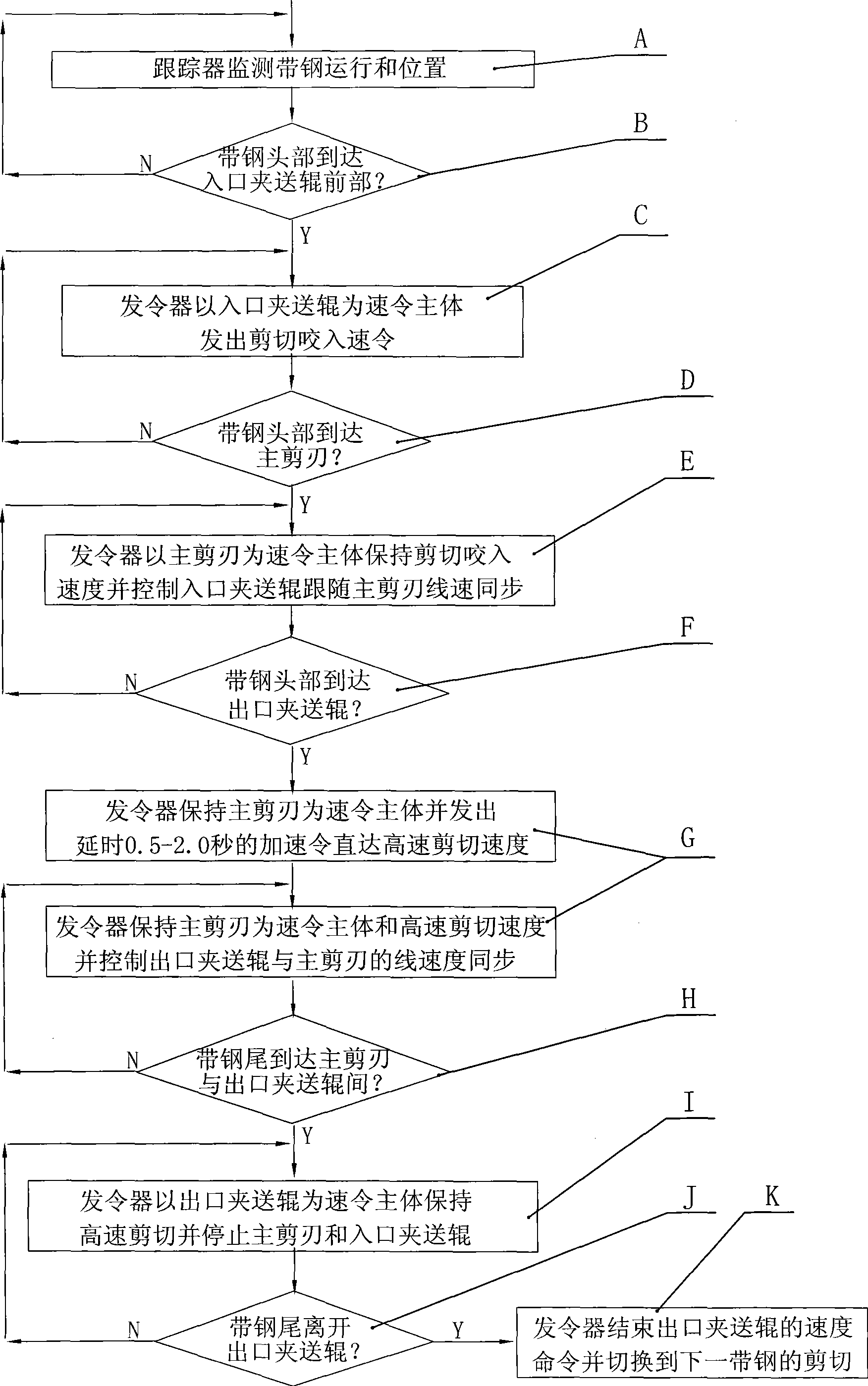
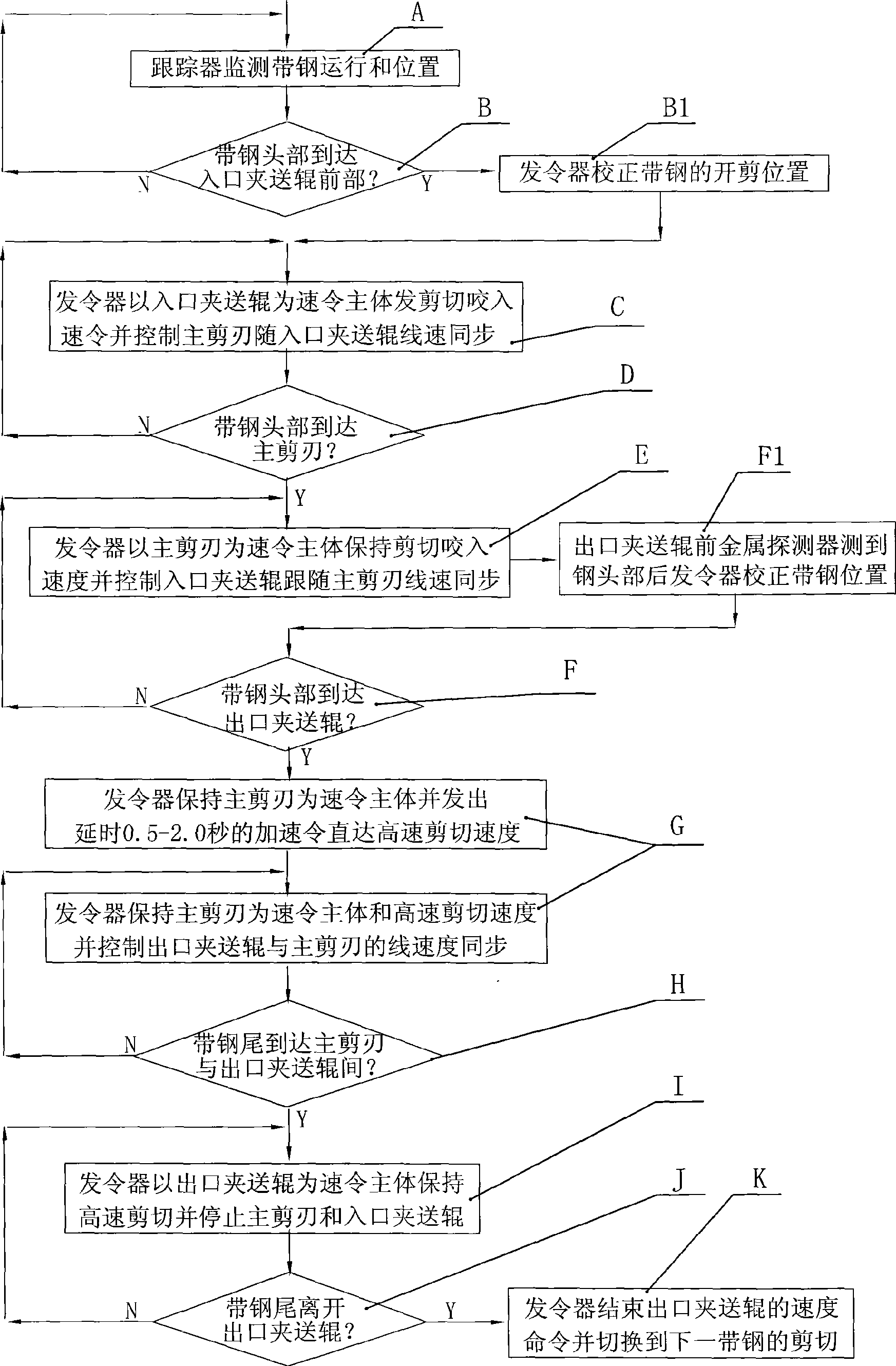
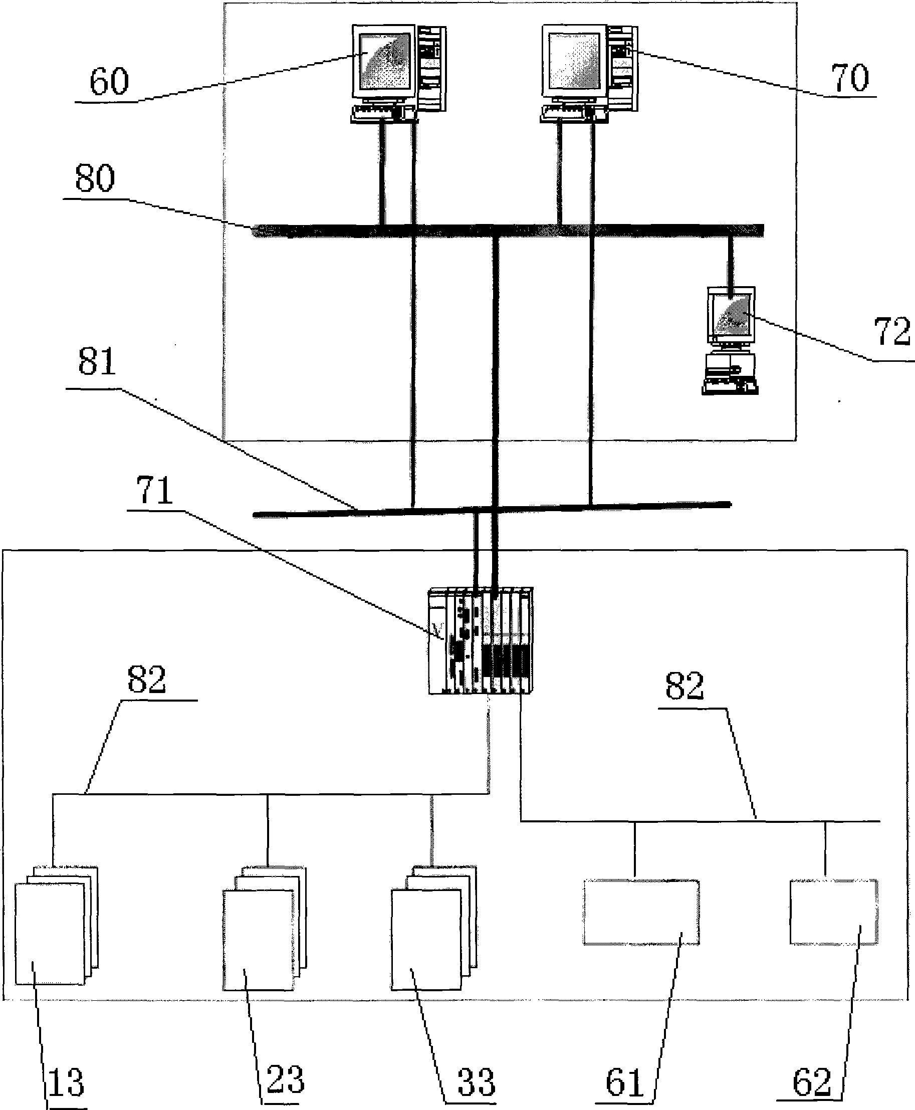
[0055] like figure 2 , is a schematic block diagram of Embodiment 2 of the method of the present invention. In this method, the disc shears include an inlet pinch roller, a main shear blade, an outlet pinch roller, and a conveying roller table, the pinch roller includes an upper roller and a lower roller, and the main shear blade includes a lower shear blade and an upper roller The cutting edge, the control device of the disc shears includes a tracker for tracking the position of the steel strip, a starter for outputting control commands, a speed regulator for each pinch roller and the main cutting edge,

[0056] The tracker includes a computer, and also includes a speed measuring sensor arranged on the side of each pinch roller lower roller 2 and the side of the main shear edge 2, and the computer collects the speed data of each speed measuring sensor and performs mathematical calculation to track the operation of the strip steel Location;

[0057] The control device also ...


PUM

PropertyMeasurementUnit
thicknessaaaaaaaaaa
lengthaaaaaaaaaa

Abstract

The invention relates to a shearing control method and a shearing control device for circle shears. The method comprises the following steps: when the head of a steel strip reaches the front parts of entrance pinch rolls, a command sender takes the entrance pinch rolls as a speed command body to send a shearing and biting speed command; when the head of the steel strip reaches a main cutting edge, the command sender takes the main cutting edge as the speed command body, maintains the shearing and biting speed, and controls the entrance pitch rolls to follow and be synchronous with the linear speed of the main cutting edge; and when the head of the steel strip reaches exit pitch rolls, the command sender takes the main cutting edge as the speed command body to send an acceleration command, controls the main cutting edge to speed up to achieve the shearing speed required in a high-speed shearing command within 0.5 to 2 seconds, and controls the exit pinch rolls to follow and be synchronous with the linear speed of the main cutting edge. The control method and the control device effectively reduce instantaneous impact loads withstood by all mechanical parts at the time of biting, prolong the service life of shearing equipment, reduce maintenance cost, reduce the failure rate of a clamping chute at a cutting edge, and improve equipment stability and utilization rate.

Description

technical field [0001] The invention relates to a steel plate processing and manufacturing equipment and technology, more specifically, the invention relates to a disc shearing equipment for rolling steel plates and a shearing control method thereof. Background technique [0002] There are currently more than 30 production lines for medium and thick steel plates in China. In the finishing area of ​​the steel rolling production line, the edge shearing equipment mainly includes two types of equipment: double-sided shears and disc shears. For the production line using disc shearing equipment, at present, the electrical drive system of the shearing machine body generally adopts frequency conversion speed regulation control, and the speed regulation range is 0-50 rpm; among them, the shearing speed below 20 rpm is commonly referred to as "low-speed shearing". Cutting", the shearing speed above 20 rpm is commonly referred to as "high-speed shearing". [0003] The shearing control...

Claims


Application Information

Patent Timeline
Patent Type & Authority Applications(China)
IPC IPC(8): G05B19/18B23D19/04
Inventor 江业泰罗廷鉴郭同铀邢宝勤钟剑鹏雷国福
Owner SGIS SONGSHAN CO LTD
Why Eureka
Try Eureka