Voltage control oscillating circuit

A voltage control oscillation and modulation circuit technology, which is applied to the automatic control of power, electrical components, electronic switches, etc., can solve the problem of increasing noise

Inactive Publication Date: 2009-05-27
REALTEK SEMICON CORP
View PDF0 Cites 6 Cited by
  • Summary
  • Abstract
  • Description
  • Claims
  • Application Information

AI Technical Summary

Problems solved by technology

Therefore, although the method adopted in the second example reduces the limit of the operating voltage and increases the voltage margin, it also increases the noise due to the mismatch of the current mirror.

Method used


Image

  • Voltage control oscillating circuit
  • Voltage control oscillating circuit
  • Voltage control oscillating circuit

Examples


Embodiment Construction

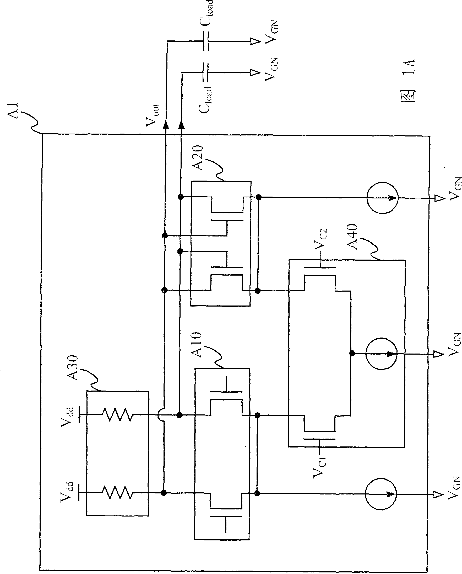
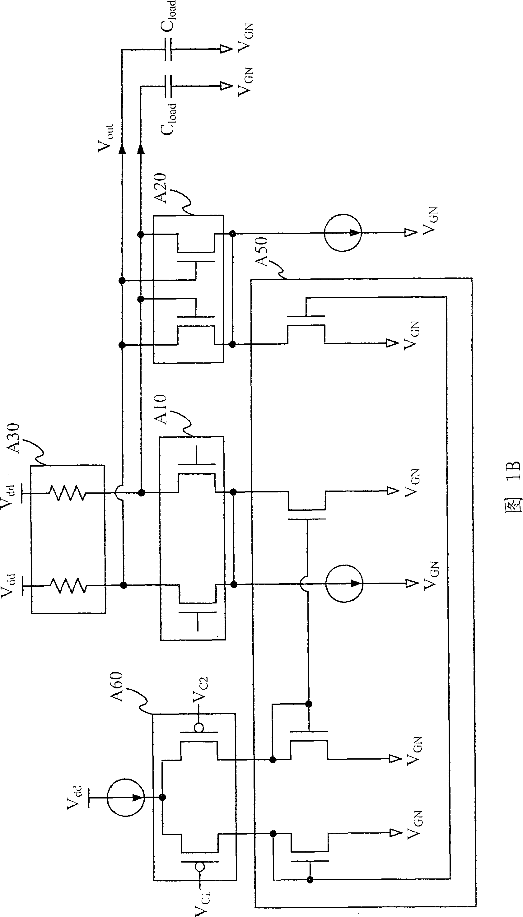
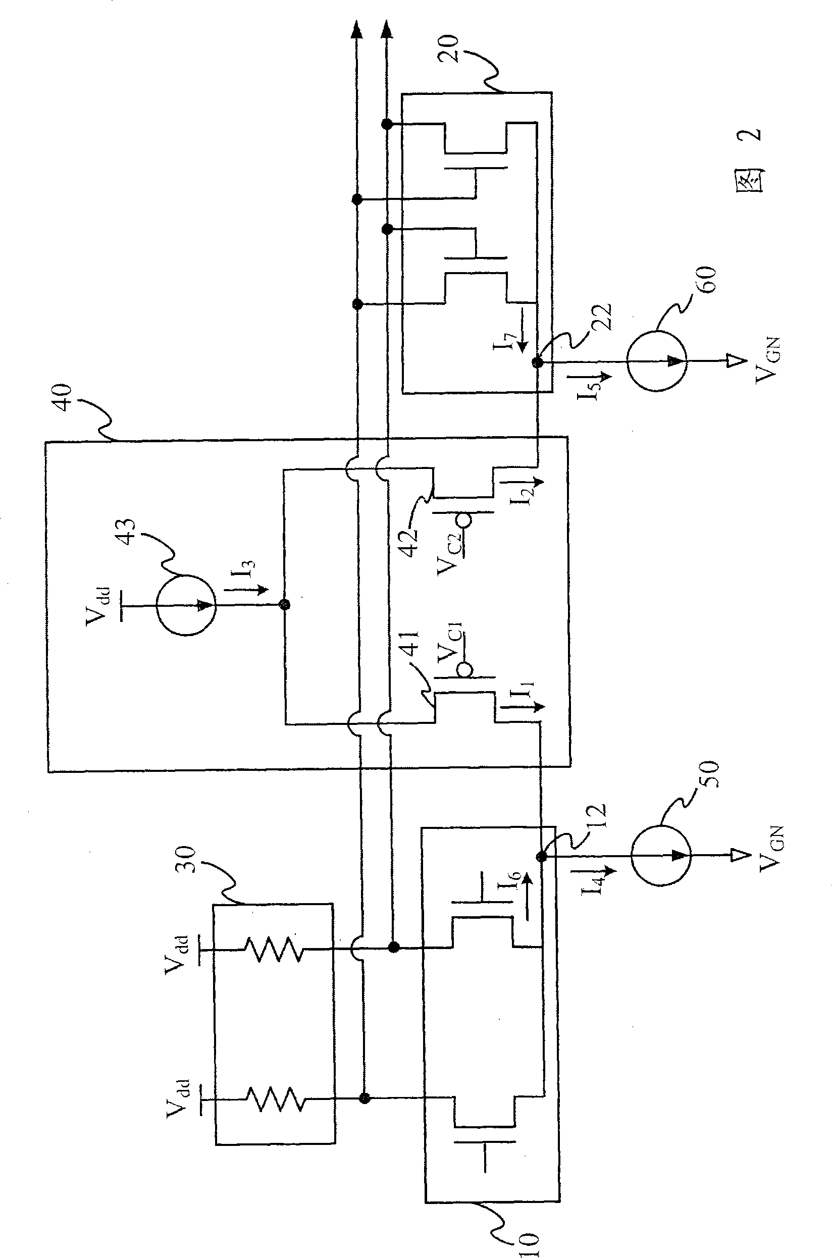
[0044] Please refer to "FIG. 2", which shows the first embodiment of the voltage controlled oscillator of the present invention. The VCO in this embodiment mainly includes: an amplifier circuit 10 , a latch circuit 20 , a load resistor 30 , a current modulation circuit 40 , an amplifier circuit terminal current source 50 , and a latch circuit terminal current source 60 . The amplifier circuit 10, the latch circuit 20, and the load resistor 30 are connected to each other in a differential configuration.

[0045] The amplification circuit 10 includes a first node 12 , and the latch circuit 20 includes a second node 22 . In this embodiment, the amplifying circuit 10 is a differential amplifier composed of two NMOS transistors, and the latch circuit 20 is a cross coupled pair composed of two NMOS transistors. The load resistor 30 is composed of a pair of resistors, one end of which is electrically connected to the amplifier circuit 10 and the latch circuit 20, and the other end i...


PUM


Abstract

The invention provides a voltage control oscillating circuit, which comprises an amplifying circuit provided with a first node, an amplifying circuit end current source, of which one end is connected with the first node and the other end is connected with grounding voltage(VGN), a latch circuit provided with a second node, a latch circuit end current source, of which one end is connected with the second node and the other end is connected with the grounding voltage, a load resistance, of which one end is electrically connected with the amplifying circuit and the latch circuit and the other end is electrically connected with power supply voltage(Vdd) and a current modulation circuit comprising a first PMOS switch, a second PMOS switch and a modulation circuit end current source, wherein the first PMOS switch is connected with the first node, the second PMOS switch is connected with the second node, one end of the modulation circuit end current source is connected with the first PMOS switch and the second PMOS switch, and the other end of the modulation circuit end current source is connected with the power supply voltage.

Description

technical field [0001] The invention relates to a voltage-controlled oscillator, in particular to a voltage-controlled oscillator applied to a current mode latch type. Background technique [0002] Generally, the output frequency curve of a traditional current mode logic (CML) latch type voltage controlled oscillator (VCO) can maintain a first-order (first-order) within a certain modulation range. characteristics. Therefore, it has the advantage of high linearity, and if it is applied in a phase locked loop (phase locked loop, PLL), the phase noise of the oscillator is relatively small. [0003] The implementation method of the traditional current-mode latch type voltage-controlled oscillator (CML-latch type VCO) is shown in "Figure 1A". The voltage controlled oscillator A1 includes: an amplifier circuit A10, a cross-coupled latch circuit (cross-coupled latch) A20, a load resistor A30, and a current modulation circuit A40. and the voltage output of the voltage controlled ...

Claims


Application Information

Patent Timeline
Patent Type & Authority Applications(China)
IPC IPC(8): H03L7/08H03L7/099H03K17/687
Inventor 曾子建
Owner REALTEK SEMICON CORP
Why Eureka
Try Eureka