

System and methods for actuation on magnetoresistive sensors
A technology for sensors and measuring sensors, which is applied in the field of biosensors and can solve problems such as changes in sensitivity
- Summary
- Abstract
- Description
- Claims
- Application Information
AI Technical Summary
Problems solved by technology
Method used
Image

Examples
example 1
[0068] Example 1: Magnetic excitation of magnetic particles followed by GMR measurement.
[0069] In a first setup, a small number of magnetic particles (eg 10 particles) close to the detection limit of the GMR sensor is allowed to stabilize under gravity for a sufficient period of time so that all the particles fall onto the surface of the GMR sensor. Determine the particle concentration on the GMR sensor.
[0070] In a second setup, magnetically actuated coils placed perpendicular to the GMR sensor surface were employed to move the same number of particles away from and towards the GMR sensor. Next, the particles may not be detected by the GMR measurement due to the altered sensitivity.
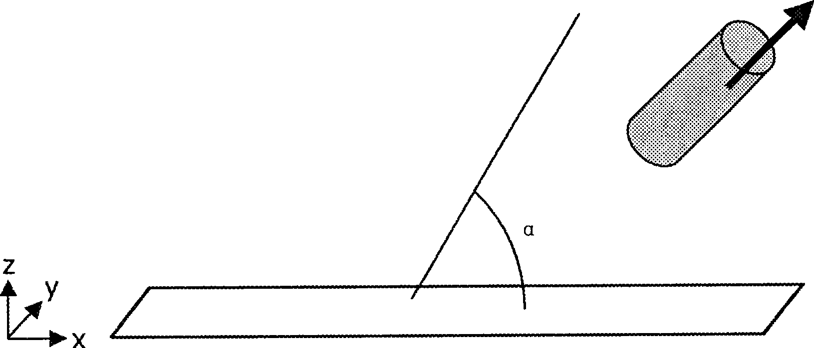
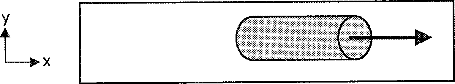
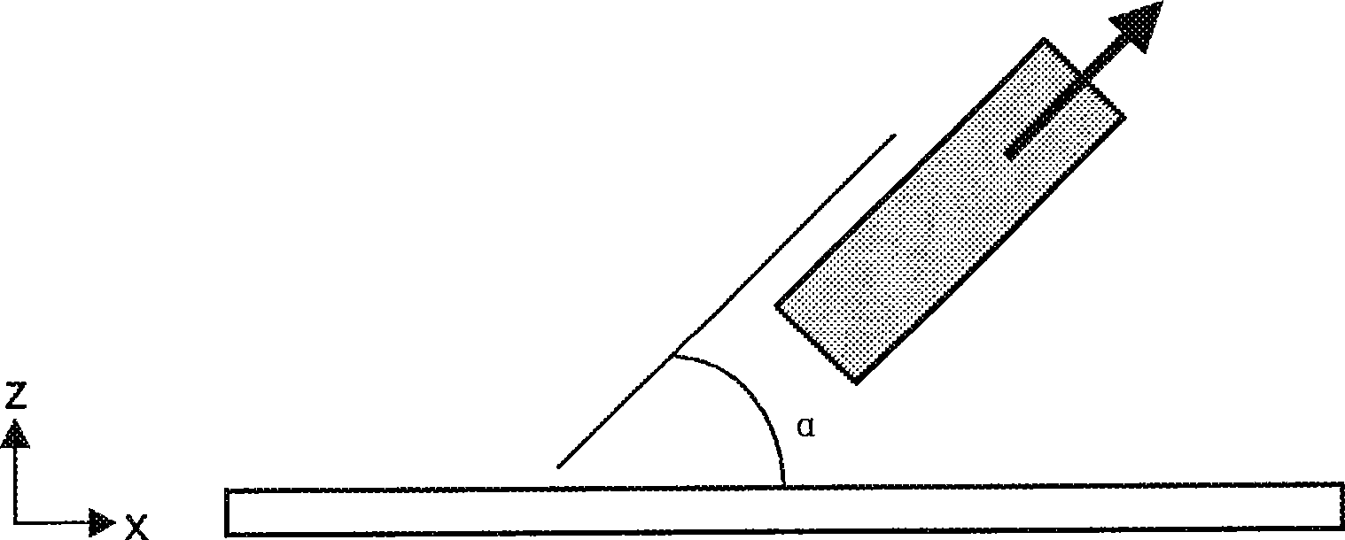
[0071] In a third setup, magnetically actuated coils positioned at an angle of 75° to the GMR sensor surface were used to move the same number of particles away from and towards the GMR sensor. At this time, particles could be detected and the concentration of particles was almost the same ...
example 2
[0072] Example 2: Magnetic Actuation and Reset on a Magnetoresistive Sensor
[0073] This example shows the effect of a magnetic actuation field and a magnetic reset field applied on a magnetoresistive sensor.
[0074] The excitation field is applied with a coil that generates a field perpendicular to the sensor surface. Align the reset coil along the long axis of the magnetoresistive sensor. No magnetic particles are present during the measurement. The current employed varied and is listed below. In use, a reset pulse is applied just before the measurement point. The sensor is always in the same state when a reset pulse is applied, independent of the excitation current. Figure 10 The measured signal of the magnetoresistive sensor is shown as a function of time. The events performed at different time points (as indicated by the arrows in the figure) are as follows:
[0075] 1: Start measurement without excitation and reset pulses.
[0076] 2: Start excitation with 250m...
example 3
[0088] Example 3: Immunoassay Using Magnetic Excitation and GMR Detection
[0089] This example shows a competition assay. A known amount of morphine was coated on the bottom of a multiwell plate. Buffer containing superparamagnetic beads (200 nm) functionalized with antibodies against morphine was added to the wells. The plate was placed on a GMR sensor and the magnetic particles were excited with a NbFeB magnet for 1 minute and 5 minutes. According to the invention, after excitation, the field at the GMR sensor is reset with a magnetic field having an in-plane component. The device was able to detect morphine with a sensitivity of about 5 to 10 ng. Moreover, with the current device, all morphine present on the plate can be detected (see Figure 11 and Figure 12 First data point of the control experiment in , where no morphine was added to the buffer).
[0090] The specificity of the assay is shown by adding free morphine to the buffer, which will compete with the anti...
PUM
| Property | Measurement | Unit |
|---|---|---|
| size | aaaaa | aaaaa |
| size | aaaaa | aaaaa |
| diameter | aaaaa | aaaaa |
Abstract
Description
Claims
Application Information