
Optical device for generating high current density picture composition electrified particle beam

A technology of charged particle beams and charged particles, applied in the field of charged particle optics, to achieve the effect of reducing beam size and uniform deposition current

Inactive Publication Date: 2009-05-27
MULTIBEAM SYST +1
View PDF3 Cites 2 Cited by
  • Summary
  • Abstract
  • Description
  • Claims
  • Application Information

AI Technical Summary

Problems solved by technology

Either of the two methods of beam positioning can be combined with either of the two methods of beam shaping, but none of these four combinations fully meets the needs of the semiconductor industry

Method used


Image

  • Optical device for generating high current density picture composition electrified particle beam
  • Optical device for generating high current density picture composition electrified particle beam
  • Optical device for generating high current density picture composition electrified particle beam

Examples


Embodiment Construction

[0093] The invention will be discussed in detail with its implementation in the field of electron beam lithography as an illustrative example. However, as outlined immediately below, many other fields of application are also conceivable.

[0094] Scanning electron microscopy typically uses a roughly Gaussian beam in order to maximize beam current density, thereby minimizing imaging time and / and maximizing the signal-to-noise ratio of the image. A disadvantage of using a Gaussian beam for microscopy is the long current tail extending away from the center of the beam, which reduces the achievable image contrast. The present invention has potential use in scanning electron microscopy, reducing the extent of these current tails, thereby improving image contrast. These same considerations can be applied to many types of scanning electron beam imaging and analysis tools, such as scanning Auger microscopes, scanning electron microscopes, scanning emission electron microscopes, etc. ...


PUM


Abstract

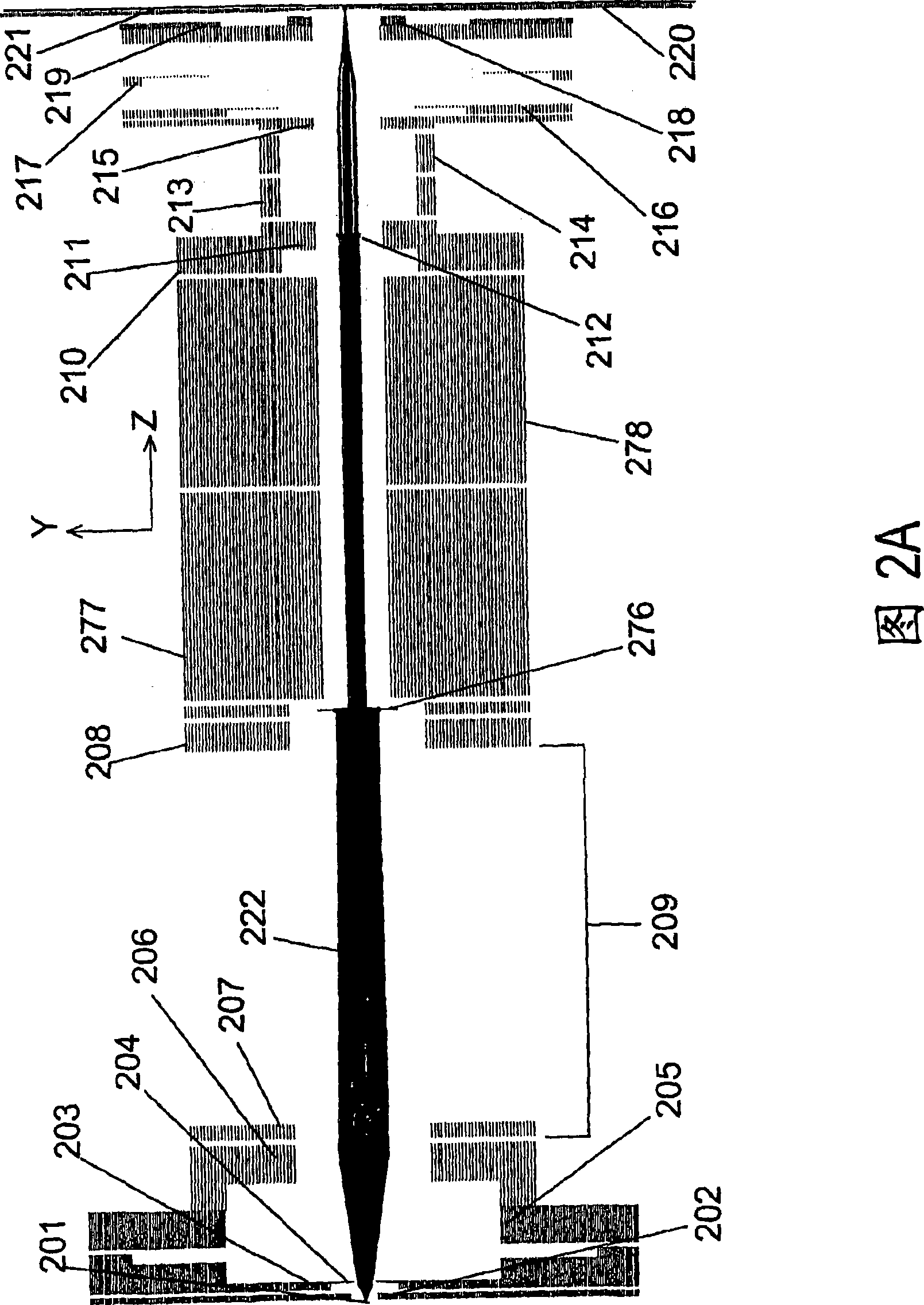
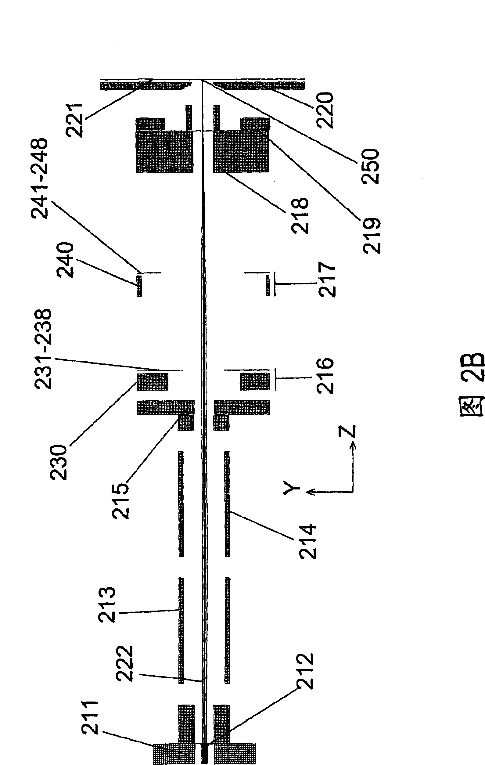
A charged particle beam lithography system and / or method, which comprises a patterned beam defining aperture (212) for generating a high current density shaped beams (222) without the need for multiple beam shaping apertures, lenses (205, 216) for focusing charged particle beams (222) on a wafer (221), and blanking deflectors (277, 278) for deflecting the charged particle beams (222) without the need for an intermediate crossover between an electron source (201) and the wafer (221).

Description

technical field [0001] The present invention relates to the field of charged particle optics, and more particularly to methods and systems for generating high current density shaped electron beams. Background technique [0002] The use of electron beams to lithographically pattern semiconductor masks, reticles and wafers is an established technique. The different write strategies used can be characterized by some key parameters: [0003] Beam Positioning Strategy [0004] There are two main methods of positioning the electron beam for resist exposure during lithography: [0005] (a) Raster scanning, where the beam moves in a regular two-dimensional lattice pattern. The advantage of this approach is that the scanning electronics are generally simpler, but the disadvantage is that the beam can spend a significant amount of time moving through areas that do not need to be exposed. Furthermore, complex grayscale and / or multi-pass scanning may be required to achieve very pre...

Claims


Application Information

Patent Timeline
Patent Type & Authority Applications(China)
IPC IPC(8): H01J37/302
CPCB82Y10/00H01J2237/31754H01J2237/30477B82Y40/00H01J2237/31793H01J2237/049H01J2237/31776H01J2237/30472H01J2237/043H01J2237/045H01J2237/10H01J2237/31761H01J37/3174
Inventor N·W·帕克
Owner MULTIBEAM SYST
Learn More