Optical fiber connector

A fiber optic connector and housing technology, applied in the field of optical fiber connectors, can solve the problems of low housing strength and difficult demoulding, and achieve good mechanical properties

Inactive Publication Date: 2009-06-03
CHINA AVIATION OPTICAL-ELECTRICAL TECH CO LTD
View PDF1 Cites 4 Cited by
  • Summary
  • Abstract
  • Description
  • Claims
  • Application Information

AI Technical Summary

Problems solved by technology

[0003] The purpose of the present invention is to provide an optical fiber connector to solve the problems of the existing optical fiber connectors that the shell strength is low and difficult to demould

Method used


Image

  • Optical fiber connector
  • Optical fiber connector
  • Optical fiber connector

Examples


Embodiment Construction

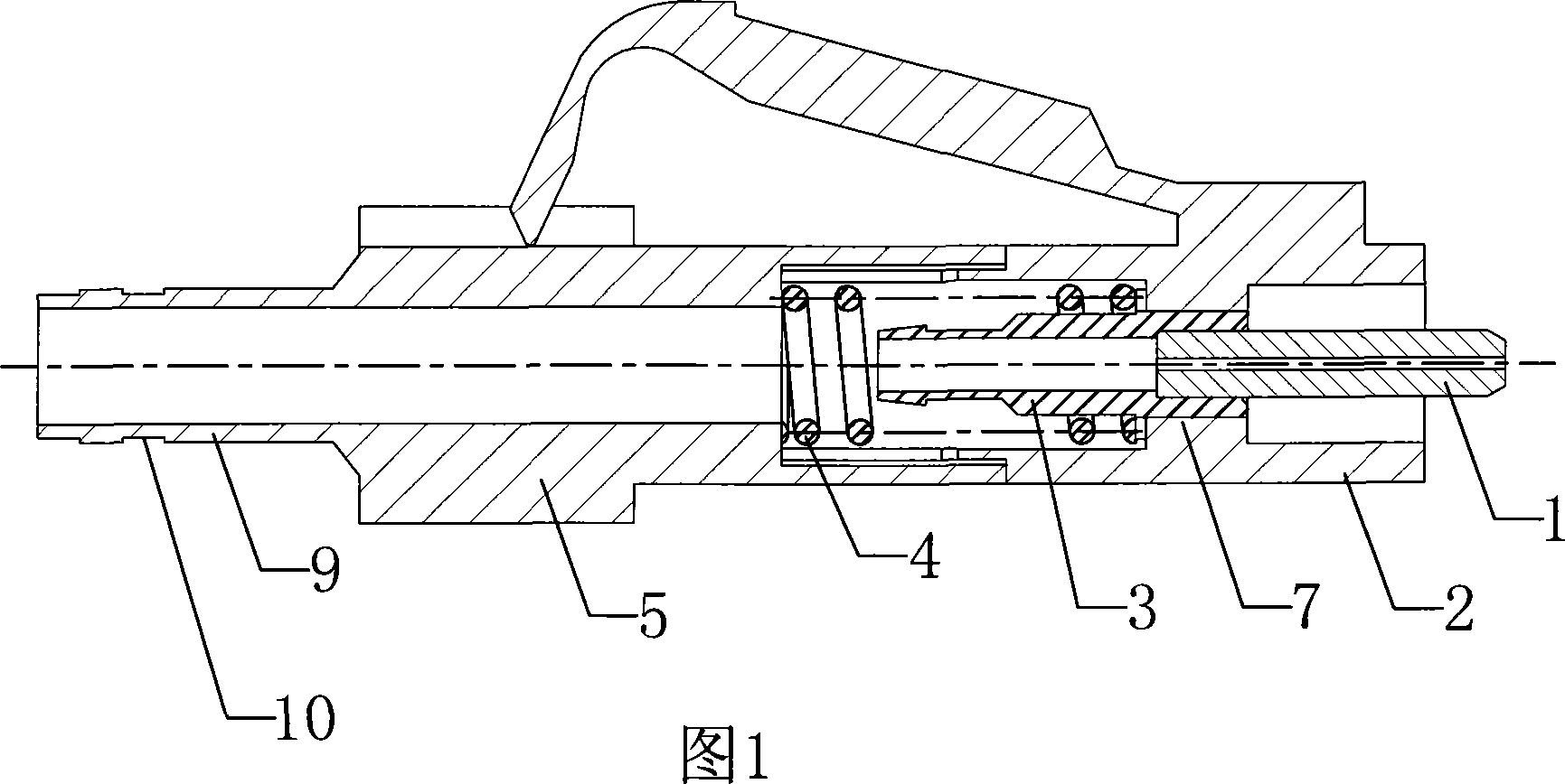
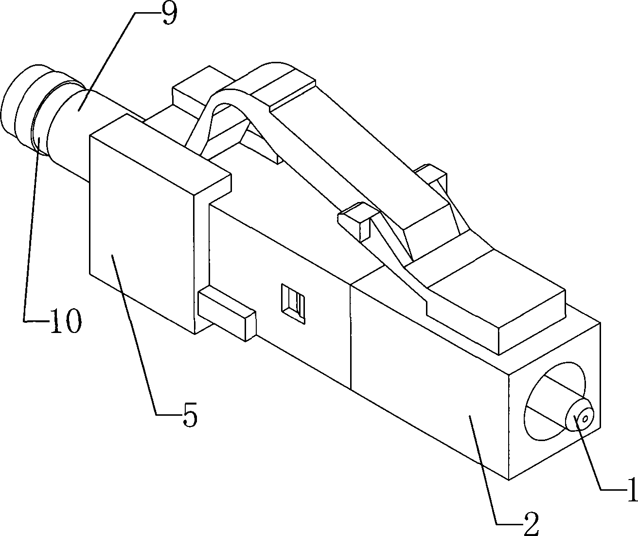
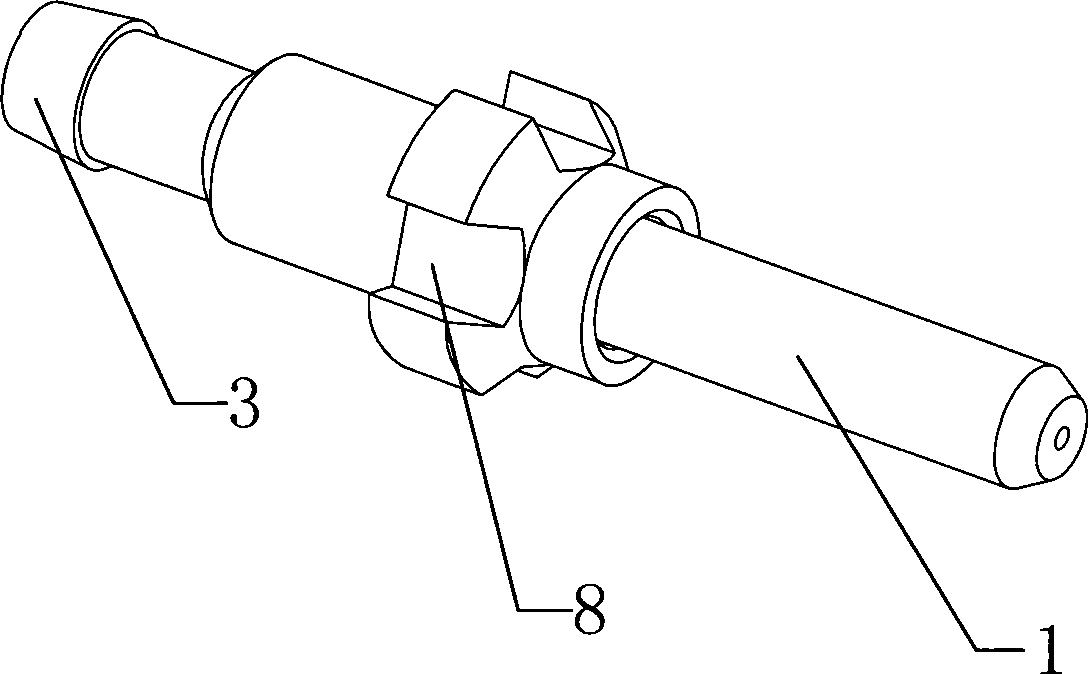
[0014] figure 1, figure 2 , image 3 , Figure 4 , Figure 5 , Image 6 An optical fiber connector of the present invention is shown, including a housing, the housing is formed by inserting the front housing 2 and the rear housing 5, the front housing is provided with a pin assembly for anti-rotation, the front housing 2 and the rear housing There is a spring installation chamber at the insertion position of the body 5, and a spring 4 is arranged in the spring installation chamber along the direction of pulling out the optical fiber connector. One end of the spring 4 acts on the rear housing 5, and the other end of the spring 4 acts on the insertion pin. on the component. The above-mentioned contact pin assembly includes a flange 3 and a contact pin 1 that is interference-fitted to the front end of the flange 3. The front face of the flange 3 is a plane, and there are four slave flanges on the circumference of the flange 3. The anti-rotation groove 8 on the front end of t...


PUM


Abstract

The invention relates to an optical fiber connector comprising a casing and a contact pin component spliced in the casing; the contact pin component includes a flange which is matched with a positioning interface arranged inside the casing; the positioning interface in the casing is a ring surface; swirl reducing grooves are uniformly formed on the periphery of the flange; swirl reducing bonds extending from the ring surface to the rear end of the casing in the axial direction of the flange are arranged in the casing; the number of the swirl reducing bonds is less than that of the swirl reducing grooves; the peripheral angle formed by each two adjacent swirl reducing bonds is an integral multiple of the peripheral angle formed by each two adjacent swirl reducing grooves; and the swirl reducing bonds are matched with the swirl reducing grooves. The optical fiber connector which adopts the technical scheme is characterized in that the swirl reducing bonds are arranged corresponding to the positions of the swirl reducing grooves formed on the flange in the casing, and serve as a strengthening rib in the casing, thereby intensifying the strength of the casing.

Description

technical field [0001] The invention relates to an optical fiber connector. Background technique [0002] Fiber optic connectors are basically an essential part of any fiber optic communication system. For example, such connectors can be used to join segments of fiber into longer lengths; to connect fiber to active components such as radiation source detectors and repeaters; or to connect fiber to devices such as switches and attenuators. passive devices. The main function of a fiber optic connector is to maintain the ends of the two fibers so that the core of one fiber is axially aligned with the core of the other; thereby coupling all of the light from one fiber to the other. This requires a fairly delicate connection, since the light-carrying region (core) of the fiber is relatively small. In a single-mode fiber, the core diameter is about 8 μm (1 μm = 10 -3 mm). U.S. Patent US6287018 discloses such a fiber optic connector: a ferrule assembly is inserted in the housi...

Claims


Application Information

Patent Timeline
IPC IPC(8): G02B6/38
Inventor 田随亮黄澄
Owner CHINA AVIATION OPTICAL-ELECTRICAL TECH CO LTD
Why Eureka
Try Eureka