
Realization method for heat-engine plant speed regulating system model in power system simulation

A speed control system and power system technology, applied in general control systems, control/regulation systems, simulators, etc., can solve the problem that the speed control system model cannot interface, does not reflect the unit coordination control system model, and cannot reflect the speed control system dynamics Features and other issues

Active Publication Date: 2009-06-03
CHINA ELECTRIC POWER RES INST +1
View PDF0 Cites 59 Cited by
  • Summary
  • Abstract
  • Description
  • Claims
  • Application Information

AI Technical Summary

Problems solved by technology

However, the units in actual operation have a variety of control methods, and most units adopt the coordinated control method instead of the BF adjustment method, so the scope of application of the model is limited
[0016] 2) Does not reflect the coordinated control system model of the unit
Therefore, the existing model is not comprehensive and cannot reflect the dynamic characteristics of the speed control system of the unit
[0018] 3) It cannot correctly reflect the primary frequency modulation characteristics of the unit
However, the existing model can only be set in DEH. Therefore, it cannot correctly reflect the primary frequency regulation characteristics of all units, which will lead to deviations in grid frequency calculation.
[0020] 4) Does not consider the interface with the whole process simulation of electromechanical transient medium and long-term dynamics
[0021] In the medium and long-term dynamic simulation, the main steam pressure of the boiler is no longer constant, so the boiler and its control system model need to be considered, but the existing model has no interface with the boiler and its control system model
In addition, for existing thermal power units that adopt a coordinated control system, if the unit participates in automatic generation control (AGC), the interface is in the coordinated control system, so the existing speed regulation system model cannot be compared with that of a thermal power unit that adopts a coordinated control system. AGC model for interface

Method used


Image

  • Realization method for heat-engine plant speed regulating system model in power system simulation
  • Realization method for heat-engine plant speed regulating system model in power system simulation
  • Realization method for heat-engine plant speed regulating system model in power system simulation

Examples


Embodiment Construction

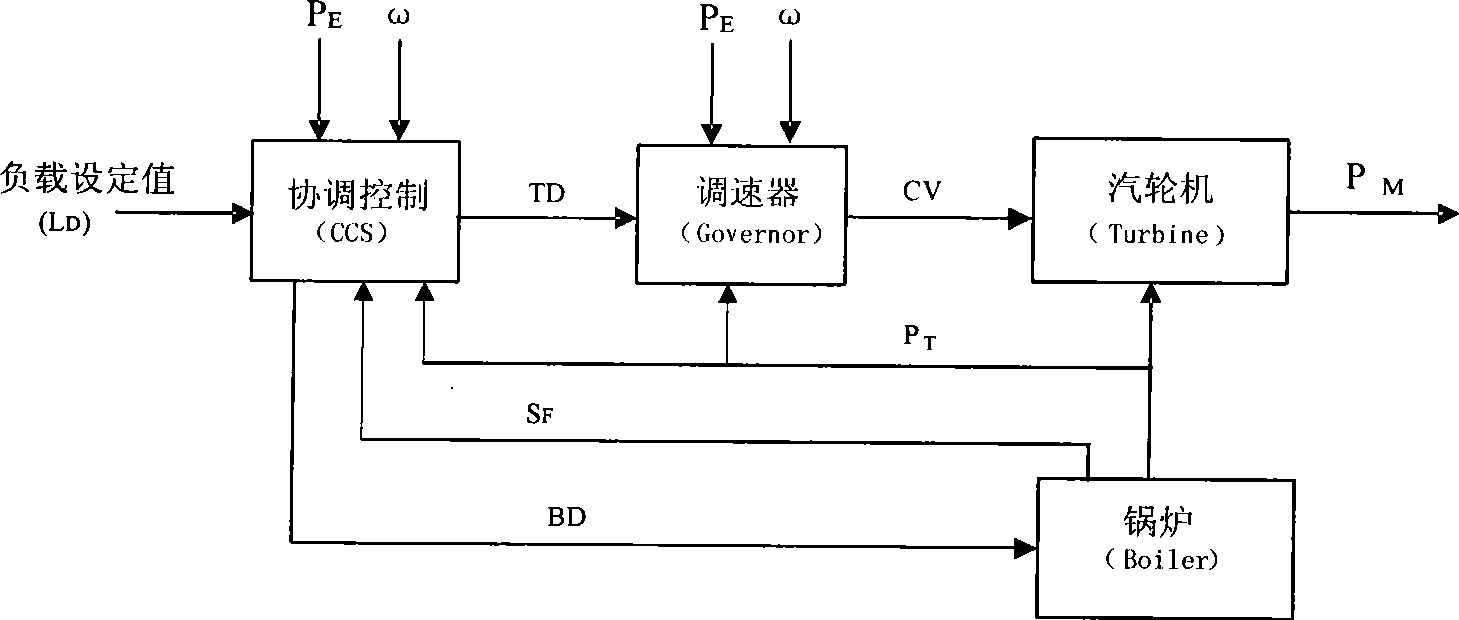
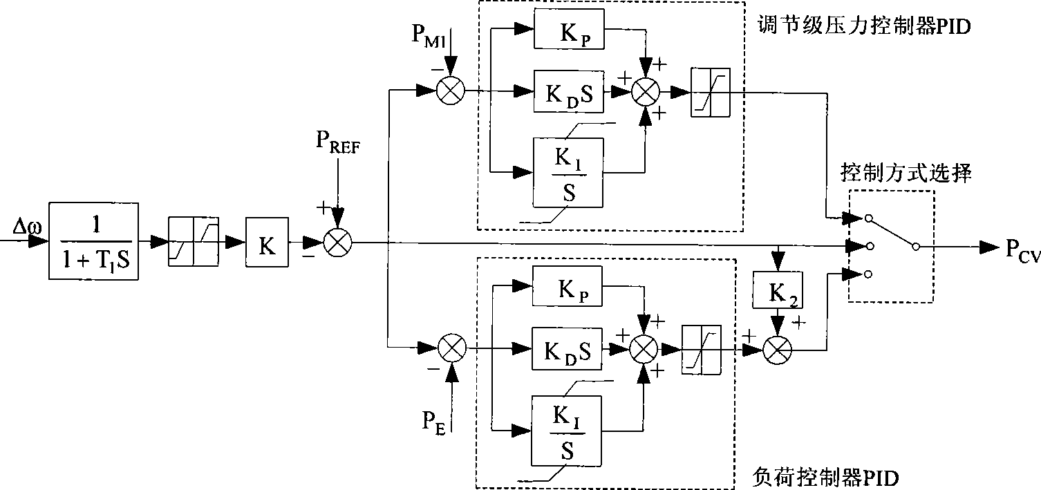
[0053] Below, refer to the attached Figure 4-8 Describe in detail the realization method of the thermal power plant speed regulation system model in the power system simulation of the present invention.

[0054] At present, most of the speed control system models of thermal power plants used in domestic power system stability simulations are similar to the typical models recommended by IEEE in 1973 (see attached figure 2 ), only simulating the steam turbine governor; although some regional power grids use the measured steam turbine governor model (see attached image 3 ), a model without a coordinated control part. However, the coordinated control system in thermal power plants has been widely used. If the dynamic characteristics of the coordinated control part are not considered, the characteristics of the speed regulation system in thermal power plants cannot be simulated accurately. Therefore, the present invention proposes a speed governing model with coordinated contr...


PUM


Abstract

The invention provides a realization method for a heat-engine plant speed regulating system model in power system simulation, wherein, not only a coordinated control system of a boiler and a steam turbine is simulated, but also a speed regulation control system of the stem turbine is simulated. A coordinated control system model comprises a realization method of the primary frequency control, the steam turbine master control, the boiler master control and the feedforward control. A model of the speed regulation control system of the steam turbine comprises a realization method of the primary frequency regulation and a valve actuator model. The realization method can correctly simulate the primary frequency regulation function of the heat-engine plant, realize different configuration ways of speed regulation control, in addition, the method can be applied to a boiler model and an automatic power generation control model and meet the requirements of the electromechanical transient state and medium-term and long-term dynamic simulation of the power system on dynamic system simulation of the heat-engine plant.

Description

technical field [0001] The invention relates to a simulation and calculation of a power system, in particular to a method for realizing a speed regulation system model of a thermal power plant in power system simulation. Background technique [0002] The digital simulation of power system has become the main tool for power system planning, design, operation and analysis. Models and parameters are important determinants of the accuracy of simulation results and directly affect the decision-making scheme based on them. In recent years, the accuracy of frequency response in power system stability simulation has attracted widespread attention from domestic and foreign power grid dispatching and research departments. The analysis of accidents related to power and frequency shows that due to the inaccurate model and parameters of the unit speed control system used in the current simulation, there is a large difference between the frequency response process in the stability simula...

Claims


Application Information

Patent Timeline
IPC IPC(8): G05B17/02
Inventor 宋新立刘肇旭李永庄汤涌刘增煌
Owner CHINA ELECTRIC POWER RES INST
Learn More