Method for time base determination of simple and convenient multi-node synchrosystem and system thereof

A synchronization system, multi-node technology, applied in the field of time reference determination, can solve the problem of impossible to change the lamp structure and installation circuit, and achieve the effect of increasing hardware cost, ensuring timing accuracy, and ensuring synchronization requirements

Inactive Publication Date: 2009-06-03
张广涵
View PDF0 Cites 37 Cited by
  • Summary
  • Abstract
  • Description
  • Claims
  • Application Information

AI Technical Summary

Problems solved by technology

[0005] If LED decorative color bulbs are installed in ordinary lamps as vulnerable parts of ordinary lamps, it is obviously impossible for them

Method used


Image

  • Method for time base determination of simple and convenient multi-node synchrosystem and system thereof
  • Method for time base determination of simple and convenient multi-node synchrosystem and system thereof

Examples


Embodiment 1

[0013] Example 1: LED moving lantern group

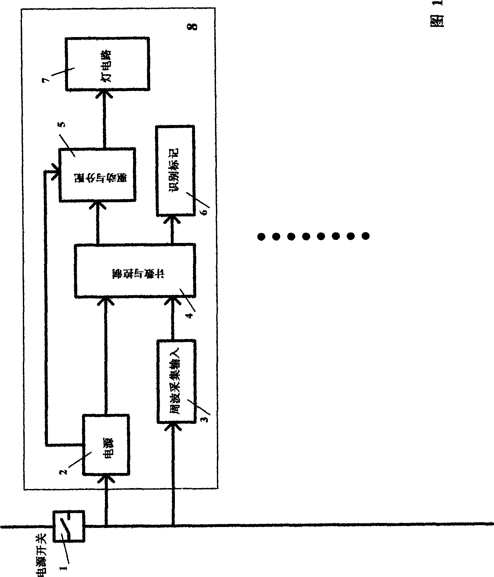
[0014] The LED moving colored lamp group designed by the present invention is composed of a plurality of independent LED moving colored lights, which are all connected to the same mains power grid inlet line and share a mains power switch. Its usage is similar to energy-saving lamps for general lighting. But it is used in groups according to the lighting effect or the number of lamp holders in the lamp. The LED moving color lamp group can be used alone as a color lamp or an advertising picture and character lamp, and can also be assembled in an ordinary lamp as a vulnerable part of an ordinary lamp. The program in each LED moving color light is different. It is written according to the arrangement of the overall lighting effect. It realizes the lighting effect by the switching sequence of the light-emitting diode and the setting power sequence. The setting power is generated by the single-chip microcomputer. driven by pulse width ...

Embodiment 2

[0018] Embodiment 2: A kind of universal synchronous controller

[0019]The controlled object of the control system is equipped with multiple intelligent control units, and each control unit is connected to the same mains grid line and shares a mains power switch. The control functions of the control system are realized by these control units. Each measurement point is measured synchronously at each set time point. After the measurement data is collected by each control unit, different given values ​​(or valve positions) are output according to a predetermined control scheme. These different output control quantities , can be determined by system control, such as attitude control correction, etc., or it can be an artificial distribution of control volume, for example, each supply pipeline of a liquid pool is determined by the investment amount of each investor in the project to determine the input control volume. The universal synchronous controller can also be used only for ...


PUM


Abstract

The invention provides a method for time base determination of simple and convenient multi-node synchrosystem and system thereof, and relates to a method for time base determination of multi-node synchronous control system which are connected with the same electric network line and share an power switch, and LED dynamic colored lights by utilizing the method and a general synchronous measurement controller. In the invention, the eigenvalue of the electric network cyclic wave is used as synchronous signals, and the signals are captured and counted; the count value is used for representing the time base run by system application program, and the timing error requirement of the control system is balanced; and the conventional timing method of time base circuits such as crystal oscillator, capacitance resistance oscillator and the like is utilized as another time reference used for representing time. The LED dynamic colored light set of the invention consists of a plurality of separated LED dynamic colored lights. The use of the light set is similar to the use of electricity-saving lamps used for lighting commonly, but the light set is used in groups according to lighting effect or the quantity of the lamp holder in luminaire. The LED dynamic colored light set can not only be used separately as colored lanterns or advertising lamps with pictures and words, but also be arranged in ordinary luminaire as the quick-wear part of the ordinary luminaire.

Description

(1) Technical field: [0001] The invention relates to a method for determining a time reference and a measurement and control system using the method. In particular, it relates to a method for determining the time reference of a simple multi-node synchronous control system connected to the same grid line and sharing a power switch, and an LED multi-lamp dynamic color lighting system (hereinafter referred to as LED dynamic color lamp) using this method. ) and a universal synchronous measurement controller using this method. (two) background technology: [0002] Existing synchronous control systems only use a time-base circuit such as a crystal oscillator or RC or IC oscillator to generate a time reference signal. If the control system is a multi-node synchronous system, the main controller needs to generate a synchronous signal. For some simple systems, the above synchronization method loses its market value, which is common in some products. [0003] For example, when multi...

Claims


Application Information

Patent Timeline
IPC IPC(8): H04J3/06H05B37/02F21S10/02F21Y101/02F21Y115/10
CPCY02B20/42Y02B20/40
Inventor 张广涵
Owner 张广涵
Why Eureka
Try Eureka