Inspection method and inspection apparatus of display panel

A display panel and inspection method technology, applied in the direction of measuring devices, optics, instruments, etc., can solve the problems of optical axis deviation, poor inspection efficiency, complex image processing procedures, etc., and achieve the effect of high-precision inspection

Active Publication Date: 2009-06-10
NIHON MICRONICS
View PDF6 Cites 17 Cited by
  • Summary
  • Abstract
  • Description
  • Claims
  • Application Information

AI Technical Summary

Problems solved by technology

[0013] However, in the methods of removing moiré fringes by image processing in Patent Documents 1 and 2, there are problems that a complicated image processing program is required, the image processing takes time, and inspection efficiency deteriorates.
[0014] In addition, in the methods of Patent Documents 3 and 4, precise control is required to accurately move the camera horizontally while focusing on the display panel, time is required to control the horizontal movement of the camera, and inspection efficiency is deteriorated. problems such as cost increase
[0015] In addition, in the method of blurring

Method used


Image

  • Inspection method and inspection apparatus of display panel
  • Inspection method and inspection apparatus of display panel
  • Inspection method and inspection apparatus of display panel

Examples


no. 1 Embodiment approach

[0035] A first embodiment of the present invention will be described below.

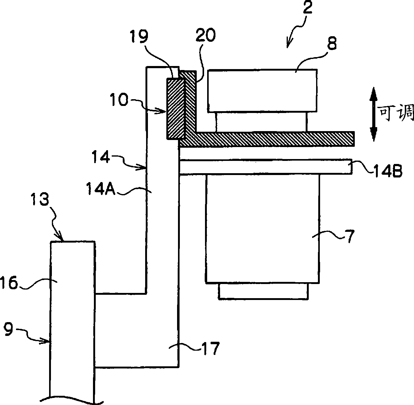
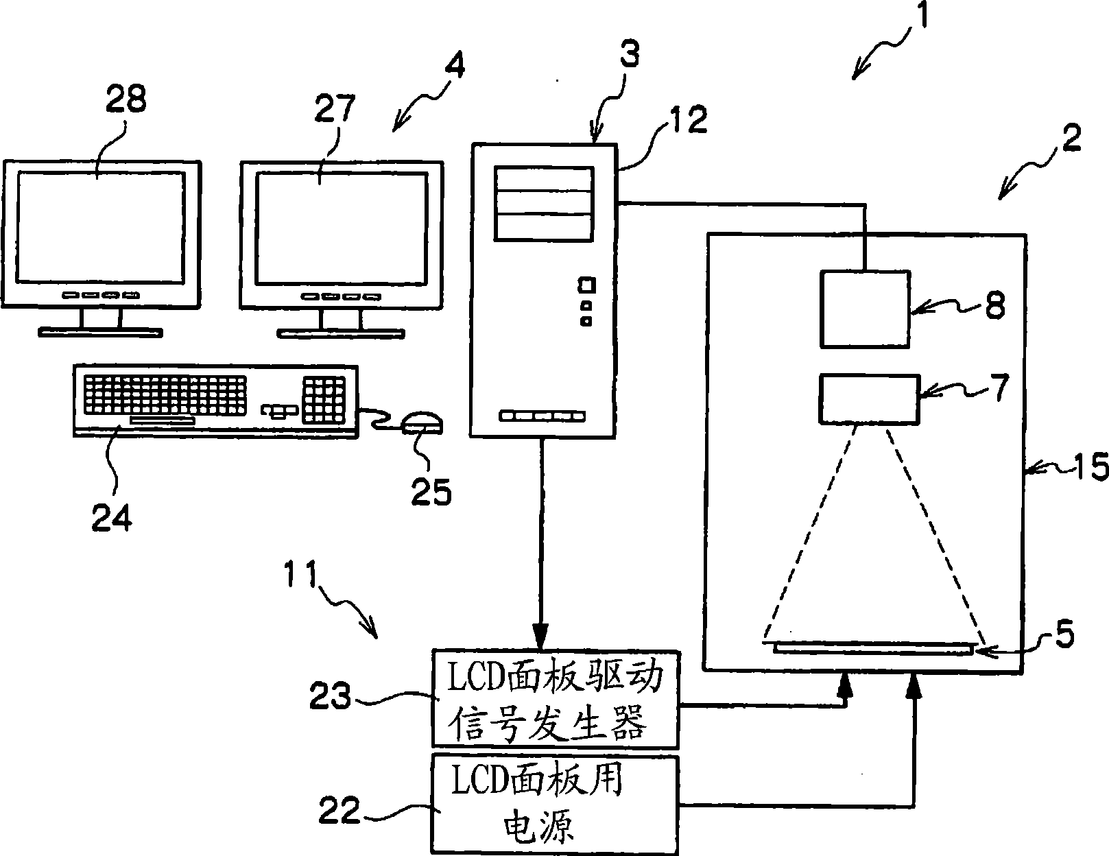
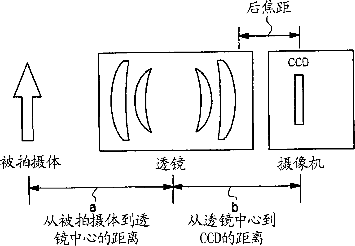
[0036] figure 1 is a configuration diagram schematically showing the imaging device of the display panel inspection device according to the embodiment of the present invention, figure 2 is a diagram schematically showing the structure of a display panel inspection device, image 3 It is an explanatory diagram schematically showing the focal length with respect to the front focal length and the back focal length of the imaging device according to the embodiment of the present invention, Figure 4 It is a graph schematically showing the brightness level distribution of the light detected by each pixel of the CCD element when the display panel is photographed by the imaging device, Figure 5 It is a graph schematically showing the brightness level distribution of the light detected by each pixel of the CCD element when the display panel is photographed by the imaging device in the state where moiré f...

no. 2 Embodiment approach

[0081] A second embodiment of the present invention will be described below.

[0082] The display panel inspection device of the present embodiment adds an optical filter to the display panel inspection device 1 of the first embodiment described above. Since the overall configuration is the same as that of the display panel inspection apparatus 1 according to the first embodiment, the same components are given the same reference numerals here, and description thereof will be omitted, and the description will focus on the optical filter.

[0083] like Figure 9 As shown, the display panel inspection apparatus according to this embodiment is provided with a filter mounting section 31 for mounting an optical filter 30 between the lens system 7 of the imaging device 2 and the imaging element 8 .

[0084] As the optical filter 30, a filter having functions required for a display panel inspection device is used. For example, select the one required for a display panel inspection d...


PUM


Abstract

The present invention provides an inspection method and device for a display panel, which may quickly and correctly inspecting display unevenness of a display panel. The method and device use a pick-up member having a lens system and a pick-up element to pick up displayed image, and inspect the display unevenness of the display panel according to the picked up image. The inspection device comprises a focusing member for focusing relative to the display panel of the pick-up member; a dispersal member for dispersing light of the image by adjusting distance between the lens system and the pick-up element, thereby restraining Moire fringe generated when picking-up the displayed image on the display panel. A light filter installation section for installing optical light filter is provided between the lens system and the pick-up element.

Description

technical field [0001] The present invention relates to the inspection of display panels such as liquid crystal displays, and particularly relates to a display that suppresses occurrence of moiré fringes (interference fringes) and light blocking when an image displayed on the display panel is captured and displayed when inspecting display unevenness of the display panel Panel inspection method and inspection device. Background technique [0002] When inspecting a display panel such as a liquid crystal display, it is known that moiré fringes are generated when an image displayed on the display panel is captured by a camera using a CCD (CCD camera). The moiré fringes are generated because the brightness of light received by pixels arranged in a regular lattice matrix changes regularly and repeatedly little by little. That is, both the display panel and the CCD are arranged in a regular lattice matrix of pixels as the unit of the displayed image, but due to the relative positi...

Claims


Application Information

Patent Timeline
IPC IPC(8): G01M11/02G02F1/13
CPCG01N21/95G01N2021/9513G02F1/1309
Inventor 金泽健太郎水野邦广菊田诚
Owner NIHON MICRONICS
Why Eureka
Try Eureka