

Light emitting unit
A light-emitting unit and light-emitting diode technology, which is applied in the direction of electrical components, semiconductor/solid-state device parts, semiconductor devices, etc., can solve the problems of not being able to improve the heat dissipation of light-emitting diodes, and achieve the effect of improving the heat dissipation effect
- Summary
- Abstract
- Description
- Claims
- Application Information
AI Technical Summary
Problems solved by technology
Method used
Image

Examples
no. 1 example
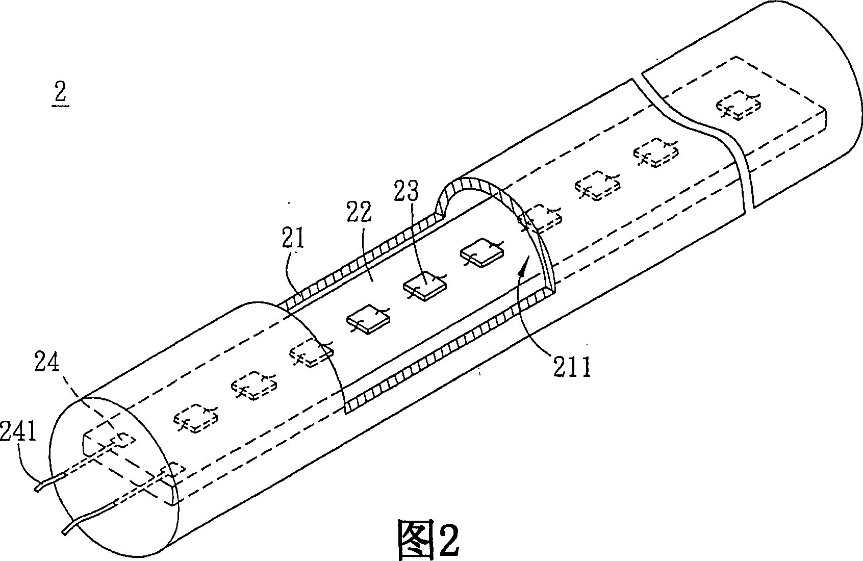
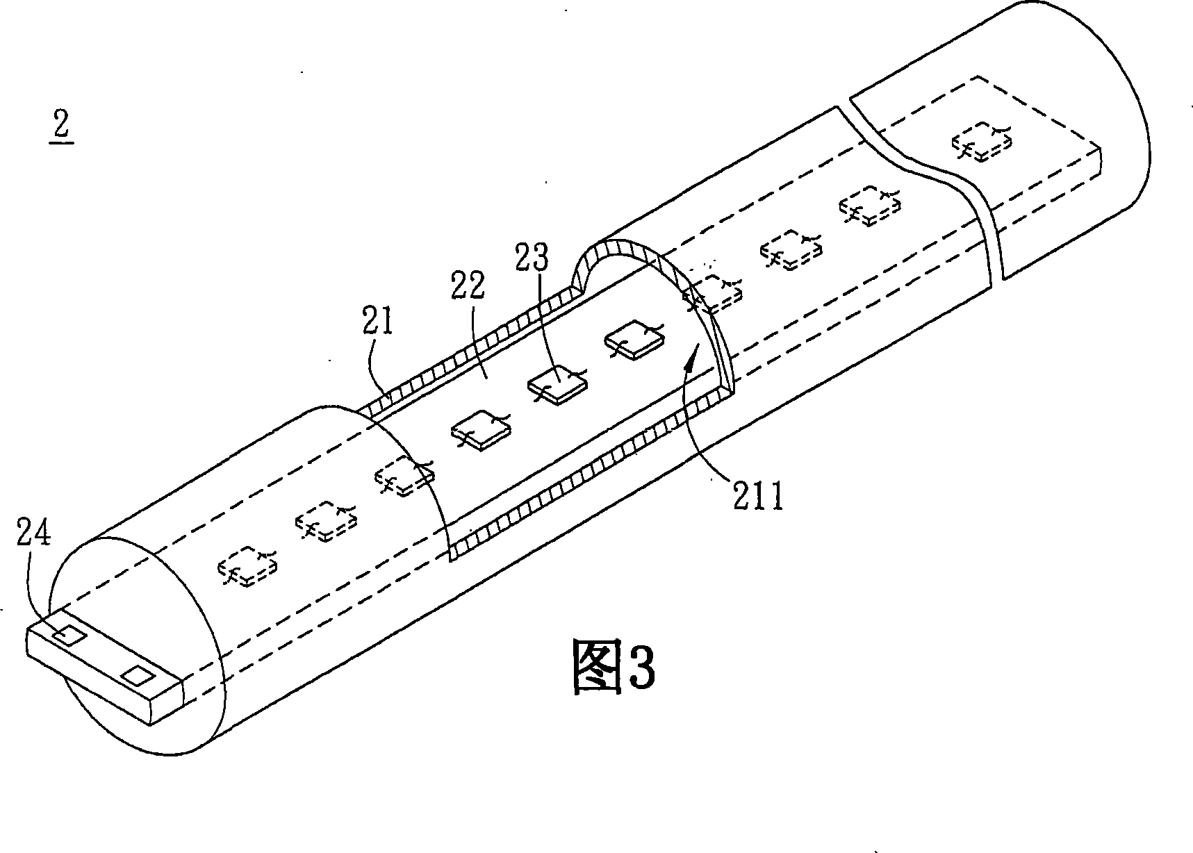
[0045] Referring to FIG. 2 , a light-emitting unit 2 according to the first embodiment of the present invention includes a light-transmitting tube body 21 , a circuit board 22 , a plurality of LED chips 23 and at least two connecting electrodes 24 .
[0046] The transparent tube body 21 is at least partly transparent and has a closed space 211. In other words, the transparent tube body 21 can have a transparent part and a non-transparent part, which means that the transparent tube body 21 can be partly transparent and partly Opaque, of course, the light-transmitting tube body 21 can also be completely light-transmitting. The enclosed space 211 can be vacuum or filled with gas, such as inert gas or nitrogen. In addition, the closed space 211 can also be filled with a colloid or a fluid, wherein the colloid is, for example, a liquid colloid or an elastic colloid, and the fluid is, for example, an oily fluid, and the refractive index of the liquid colloid, elastic colloid or oily...
no. 2 example
[0057] Please refer to Figure 5A and Figure 5B shown, where Figure 5B It is a sectional view along the line A-A in Fig. 5A. The difference between the light emitting unit 2A of the second embodiment of the present invention and the first embodiment is that the light emitting unit 2A further includes a reflective portion and a fluorescent conversion material 26 . Wherein, the reflective portion can be a part of the light-transmitting tube body 21 , or a reflective layer 25 can be added as described in this embodiment.
[0058] In this embodiment, the reflective layer 25 is disposed on the outer surface of the transparent tube body 21 and has at least one opening 251 corresponding to a light emitting surface of the LED die 23 . The material of the reflective layer 25 is selected from one of the ultraviolet light band (200-400nm), the visible blue light band (400-480nm) or the full visible light band (400-780nm) in the reflection spectrum, and its reflectivity is at least gre...
no. 3 example
[0070] Based on the above, the light-transmitting tube body of the light-emitting unit can be formed integrally as described above, and can also be composed of at least two shell elements. Please refer to Figure 10A and Figure 10B As shown, a light-transmitting tube body 41 of the light emitting unit 4 is composed of two shell elements 412 , 413 . A plurality of LED chips 43 and two connecting electrodes 44 are also disposed on the circuit substrate 42 , and the circuit substrate 42 is sandwiched between the two housing components 412 , 413 . Wherein, a reflective layer 45 can be arranged or formed on the circuit substrate 42, and a fluorescent conversion material 46 can be arranged or formed on the casing element 412, but it is not limiting, and its variations can also refer to the above-mentioned Example. In addition, since the light-transmitting tube body 41 can have a light-transmitting portion and a non-light-transmitting portion, which means that it can be partly li...
PUM
 Abstract
Description
Claims
Application Information