Steel truss-steel plate combined shear wall and method for producing the same

A technology of combining shear walls and manufacturing methods, applied in the direction of walls, structural elements, building components, etc., can solve the problems of large stress, impact on seismic capacity, and reduce the bearing capacity of shear walls, so as to reduce self-weight, improve bearing capacity, The effect of improving the shear capacity

Inactive Publication Date: 2009-06-17
BEIJING UNIV OF TECH
View PDF0 Cites 10 Cited by
  • Summary
  • Abstract
  • Description
  • Claims
  • Application Information

AI Technical Summary

Problems solved by technology

However, when the steel plate in the steel plate shear wall is stressed, the stress on the diagonal direction is the largest, and most of the damage occ...

Method used


Image

  • Steel truss-steel plate combined shear wall and method for producing the same
  • Steel truss-steel plate combined shear wall and method for producing the same
  • Steel truss-steel plate combined shear wall and method for producing the same

Examples


Embodiment 1

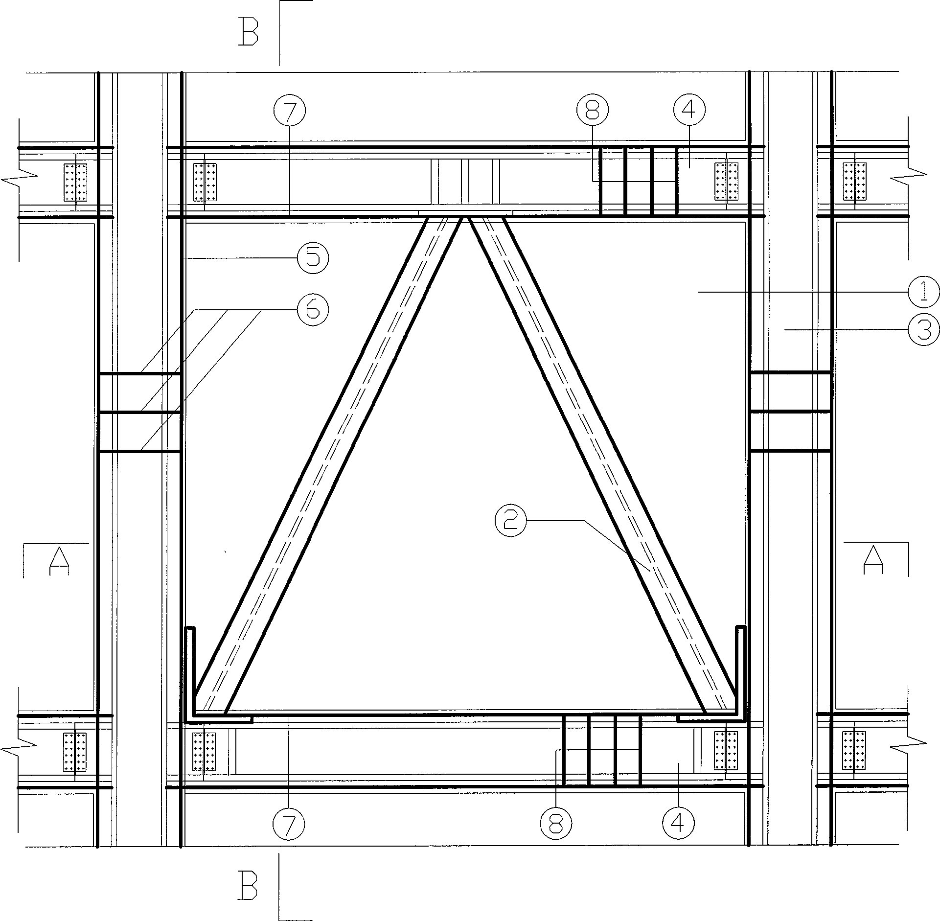
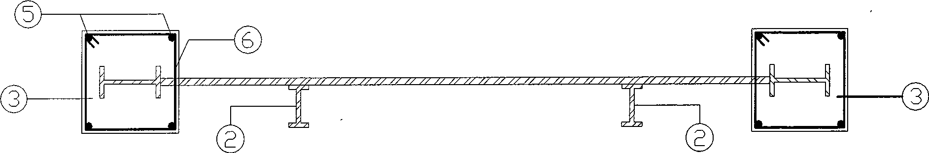
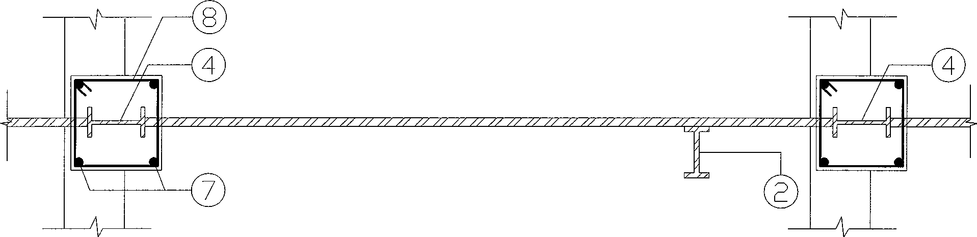
[0029] The schematic diagram of structural reinforcement of a structural unit of steel truss-steel plate composite shear wall is as follows Figure 1 ~ Figure 3 shown. This embodiment is composed of frame beams, shaped steel concrete columns 3, steel plates and shaped steel oblique supports. The two ends of the shear wall are provided with steel concrete columns 3, and the steel concrete columns 3 are consolidated with the frame beams, and a steel plate 1 is arranged between the frame beams and the frame columns, and holes or grooves are reserved on the steel plate 1. The frame beam of the shear wall is provided with a shaped steel beam 4, and the frame beam longitudinal reinforcement 7 is arranged on the periphery of the shaped steel beam 4, and the rectangular stirrup 8 is evenly bound along the frame beam longitudinal reinforcement 7, and the rectangular stirrup 8 of the frame beam passes through The reserved holes or cutting grooves on the steel plate are evenly distribut...

Embodiment 2

[0041] The structure of this embodiment is as Figure 4 As shown, it is basically the same as in Embodiment 1, the only difference is that: the shaped steel diagonal support 2 is arranged in an X shape in the plane of the steel plate, and its upper end extends into the joint between the shaped steel concrete column 3 and the upper frame beam, and is connected with the shaped steel concrete column 3 The shaped steel in the frame and the shaped steel beam 4 in the upper frame beam are connected at the same time. The lower end extends into the node of the shaped steel concrete column and the lower frame beam, and is simultaneously connected with the shaped steel in the shaped steel concrete column 3 and the shaped steel beam 4 in the lower frame beam.

Embodiment 3

[0043] The structure of this embodiment is as Figure 5 As shown, it is basically the same as that of Embodiment 1, the only difference is that the shaped steel oblique support 2 is arranged in a figure-eight shape in the plane of the steel plate, and its upper end extends into the upper frame beam and is fixedly connected with the shaped steel beam 4 in the beam, and its lower end extends Into the node of the steel concrete column 3 and the lower frame beam, and connect with the steel beam 4 in the steel concrete column 3 and the lower frame beam at the same time.


PUM


Abstract

The invention relates to a shear wall, in particular to a steel truss-steel plate combined shear wall and a manufacturing method thereof. The shear wall comprises a frame beam, a frame pillar fixedly combined with the frame beam and a steel plate arranged between the frame beam and the frame pillar; wherein, the frame beam comprises a profile steel beam and concrete poured outside the profile steel beam to form a profile steel-concrete compound beam; the frame pillar is a profile steel-concrete pillar composed of the profile steel and the concrete poured outside the profile steel; the profile steel in the profile steel-concrete pillar is fixedly connected with the steel plate and the profile steel beam in the frame beam; a profile steel raking prop is fixedly combined on the plane of the steel plate along the oblique direction, and is distributed in a herringbone, an X shape or a reverse V shape. The profile steel beam, the profile steel-concrete pillar, the profile steel raking prop and the steel plate are combined with each other to form a steel truss-steel plate combined structure. Compared with the existing shear wall, the steel truss-steel plate combined shear wall has higher initial rigidity and carrying capacity, slower attenuation of carrying capacity and rigidity, better whole shakeproof and energy consumption performance as well as comparatively stable later period shakeproof performance, and can effectively relieve the damage caused by cutting and gliding at the bottom.

Description

technical field [0001] The invention relates to a shear wall, in particular to a steel truss-steel plate composite shear wall and a manufacturing method thereof. technical background [0002] With the development of social production and the needs of people's lives, there are more and more high-rise buildings. Reinforced concrete high-rise buildings with large volume and wide area are usually composed of beams, columns, floors, shear walls and cylinders. The shear wall and the cylinder composed of the shear wall are the core parts of the high-rise building's seismic resistance, and the seismic performance of the shear wall structure plays a vital role in the safety and reliability of the high-rise building. [0003] Because high-rise buildings need to have greater lateral stiffness, the design of shear walls must consider the design of lateral force resistance. In addition, shear walls also require large elastic initial stiffness, large deformation capacity, good plastic p...

Claims


Application Information

Patent Timeline
IPC IPC(8): E04B2/56E04C2/26E04C5/02E04B1/98
Inventor 曹万林彭斌张建伟张文江周中一董宏英
Owner BEIJING UNIV OF TECH
Why Eureka
Try Eureka