
Band-width optimized multi-mould optical fiber and method of manufacturing the same

A manufacturing method and technology for multimode optical fibers, which can be applied to graded-index core/clad optical fibers, clad optical fibers, and manufacturing tools, etc., and can solve the problems of sharpness or depression in the center of the refractive index profile, large aberration, etc., to eliminate the The effect of tipping and sag, improving uniformity, good economic benefits and application prospects

Active Publication Date: 2009-06-17
FENGHUO COMM SCI & TECH CO LTD +1
View PDF3 Cites 11 Cited by
  • Summary
  • Abstract
  • Description
  • Claims
  • Application Information

AI Technical Summary

Problems solved by technology

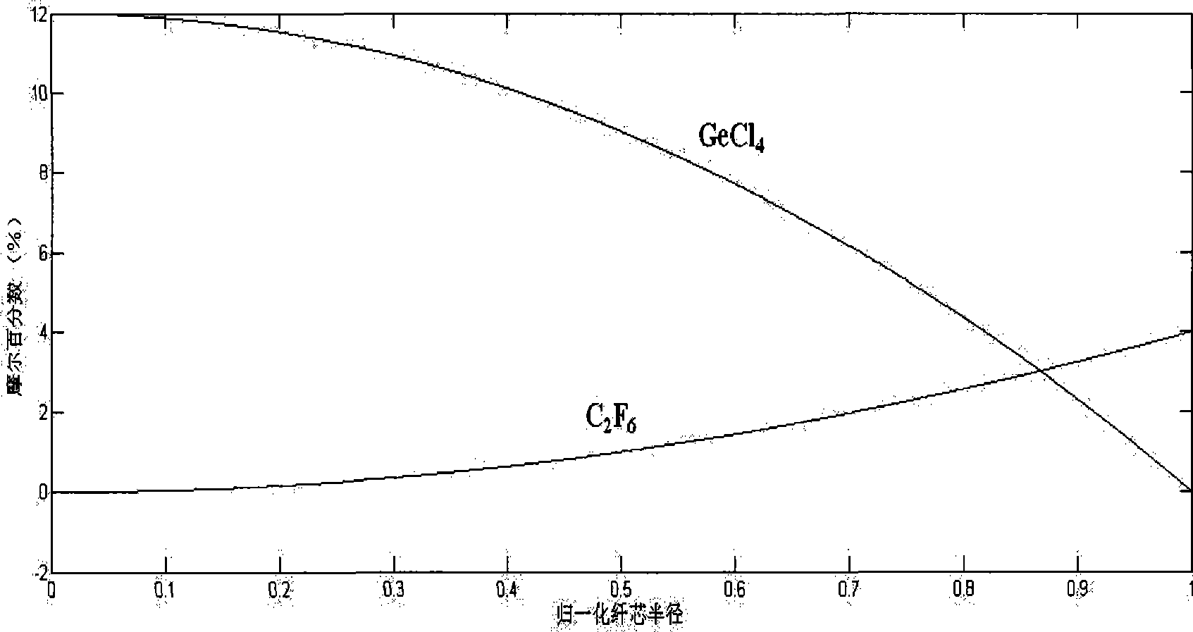
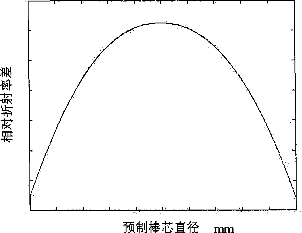
[0006] Problems to be solved by the present invention: Aiming at the problems existing in the existing multimode optical fiber manufacturing process, the actual refractive index profile parameters of the multimode optical fiber are quite different from the ideal refractive index profile parameters, and the center of the refractive index profile appears sharp or depressed. , reduce the intermodal dispersion and delay of multimode fiber, improve the transmission bandwidth of multimode fiber and the transmission capacity of high-speed network

Method used


Image

  • Band-width optimized multi-mould optical fiber and method of manufacturing the same
  • Band-width optimized multi-mould optical fiber and method of manufacturing the same
  • Band-width optimized multi-mould optical fiber and method of manufacturing the same

Examples


Embodiment Construction

[0029] The present invention will be further described below in conjunction with the accompanying drawings and specific embodiments.

[0030] The present invention relates to the following terms:

[0031]Deposition: the process in which optical fiber raw materials undergo a chemical reaction in a certain environment to form doped quartz glass;

[0032] Melting: the process of gradually firing the deposited hollow glass tube into a solid glass rod under a certain heat source;

[0033] Sleeve: a high-purity quartz glass tube with a certain cross-sectional area and uniform size;

[0034] Substrate tube: high-purity quartz glass tube for deposition;

[0035] Refractive Index Profile (RIP): The relationship between the refractive index of an optical fiber or an optical fiber preform (including an optical fiber core rod) and its radius;

[0036] Absolute refractive index difference (δn): the difference between the refractive index of each part in the optical fiber preform and the...


PUM

PropertyMeasurementUnit
diameteraaaaaaaaaa
diameteraaaaaaaaaa

Abstract

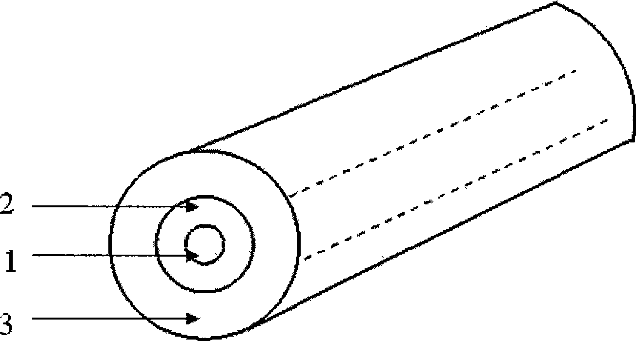
The invention relates to a bandwidth optimized multimode fiber and a manufacturing method thereof. The multimode fiber comprises three parts, including a fiber core, a quartz glass cladding and a coating with graded index profile. By adopting the method of optimizing the impurity gas flow curve, the refractive index profile parameter of a fiber core is controlled to optimize the optimal bandwidth of the fiber at the communication window of 850nm.The largest change of the differential mode time delay of the fiber is less than 0.22ps / m, the over-filled launch bandwidth is larger than 3,500MHz.km and 500MHz.km respectively at 850nm and 1,300nm and the valid mode bandwidth is larger than 4,700MHz.km and 500MHz.km respectively at 850nm and 1,300nm.The multimode fiber of the invention decreases the chromatic dispersion between modes and the time delay and increases transmission bandwidth, thereby not only meeting the application requirement of a low speed network, but also meeting the application requirement of a gigabit high speed broadband network.

Description

technical field [0001] The invention relates to a multimode optical fiber and a manufacturing method thereof, in particular to a multimode optical fiber for 10 Gigabit Ethernet in the field of optical fiber communication and a manufacturing method thereof. Background technique [0002] With the rapid development of Internet services, the demand for bandwidth in the information society is increasing day by day. In order to make full use of the bandwidth of the backbone network, people use Dense Wavelength Division Multiplexing (DWDM) technology, but the low-bandwidth connection of the access network makes the bottleneck problem in the network gradually prominent. Therefore, 10Gbit / s Ethernet technology emerges as the times require. It solves the bottleneck problem of low-bandwidth access and high-bandwidth transmission, is compatible with existing LAN technologies, and reduces network complexity. At the same time, the development and application of a new cheap laser VCSEL (V...

Claims


Application Information

Patent Timeline
Patent Type & Authority Applications(China)
IPC IPC(8): G02B6/028G02B6/02C03B37/01C03C13/04
Inventor 陈伟李诗愈王彦亮雷道玉罗文勇胡鹏王冬香胡福明
Owner FENGHUO COMM SCI & TECH CO LTD
Learn More